LCD displays can also be classified as passive and active depending on nature of the activation circuit. Passive displays use components that do not supply their own energy to turn on or turn off the desired pixels. These have a set of multiplexed transparent electrodes arranged in a row/column pattern. To address a pixel, the column containing the pixel is sent a charge and the corresponding row is connected to ground. Passive displays can have either direct drive or multiplexed drive circuitry.
However, for larger displays it is not possible and economical to have separate connections for each segment. Also, as the number of multiplexed lines increase, the contrast ratio decreases due to the cross-talk phenomenon wherein a voltage applied to the desired pixel causes the liquid crystal molecules in the adjacent pixels to partially untwist.

Download Source Code: click Here
These inherent problems of passive displays are removed in active displays. Active displays use an active device such as a transistor or a diode for each pixel which acts like a switch that precisely controls the voltage that each pixel receives. Active displays are further classified as thin film transistor (TFT) displays and thin film diode (TFD) displays depending upon whether the active device used is a transistor or a diode.
In both these devices, a common electrode is placed above the liquid crystal matrix. Below the liquid crystal is a conductive grid connected to each pixel through a TFT or a TFD. Gate of each TFT is connected to the row electrode, the drain to the column electrode and the source to the liquid crystal. The display is activated by applying voltage to each row electrode line by line. A major advantage of active displays is that nearly all effects of cross-talk are eliminated.
As LCD displays are not active sources of light, these offer such advantages as very low power consumption, low-operating voltages and good flexibility. However, their response time is too slow for many applications. They are also temperature sensitive and offer limited viewing angles.
LCD signals
 LCD displays are available typically in 8×2, 16×2, 20×2 or 20×4 formats; 20×2 means two lines of 20 characters each. These displays come with an LCD controller that drives the display. Fig. 5 shows the interface of LCD display with an FPGA.
There are three control lines namely EN (Enable), RS (Register Select) and R/W (Read/Write). EN line is used to instruct the LCD that the master controller is sending data. It is used by the LCD to latch information present on the data pins. When data is applied to the data pins, a high-to-low pulse must be applied to the EN pin so that the LCD latches the data present at the data pins. The minimum Enable signal pulse width required is 450ns.
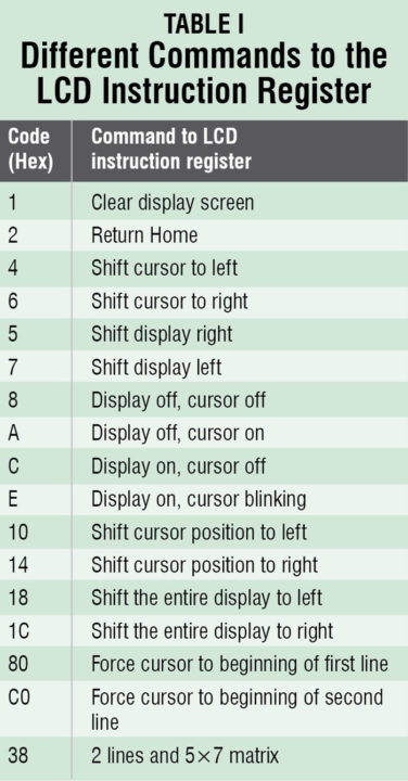
The RS pin is used to select the register to which the data has to be stored to. LCD has two registers to store the data depending upon its nature, namely, the instruction command code register and the data register. When the RS pin is high, data is sent to the data register. the data is a text data to be displayed on the LCD. When RS pin is low, the data is treated as command or instruction to the LCD module and is stored in the instruction command code register. When R/W pin is low, the instruction on the data bus is written on the LCD. When R/W pin is high, it means that the data is being read from the LCD. The different commands to the LCD instruction register are shown in Table I.
The 8-bit data bus is used to send information to the LCD or read the contents of the LCD’s internal registers. Sometimes, 4-bit bus is also used to send information. To display letters and numbers, we send their ASCII codes.
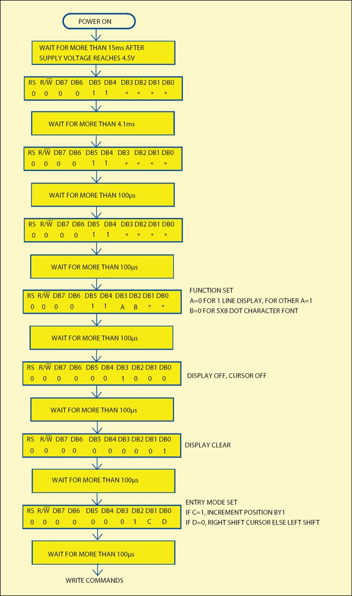
The software routine initialises the LCD first by setting the width of the data bus, selecting the character, font etc, clearing the LCD, turning on the LCD module and the cursor, setting the cursor position and so on. Then the data to be displayed is sent on the data lines. The different steps for driving the LCD are described in the following paragraphs.
Before using the LCD for display it has to be initialised (see Fig. 6). The LCD can be initialised either by using the internal reset circuit or by sending a set of commands to the LCD. The choice is of the designer, but the second method is more popular. The internal reset circuit is highly dependent on the power supply.


