 Error correction and detection has great practical importance in maintaining data and ensuring that information is transferred intact from source to destination. Also, MATLAB based graphical user interface (GUI) for convolutional code (CC) provides basic concepts of CC, its encoder structure, and classification and decoding techniques.
CCs are widely used as channel codes in practical communication systems for error correction. Encoder design consists of current bits and previous bits that are stored in shift registers. Encoded output sequence is generated from present and previous message bits. Encoded output is passed to the decoder and the decoding algorithm, which is used in Viterbi decoding algorithm.
Presented here is a project in which we design CCs for various code rates. The encoder of the designed CC is based on the code rate chosen by the user. Once the code is encoded, random noise can be added to the encoded sequence. The decoder is used to decode the message; at output, original message is obtained. Performance is evaluated with bit errors, which are the number of errors after binary sequence is decoded.
There are two major parameters on which CCs are based—code rate and constraint length. Code rate is defined as the number of current bits to the number of outputs, whereas constraint length is defined as the number of bits stored in each shift register, including the current bit.
Note. In order to run this application, a 32- or 64-bit operating system with MATLAB software is needed. The designed GUI panel/program is user-friendly. Different buttons are used in this project, and the entire working of the project is performed through push buttons.
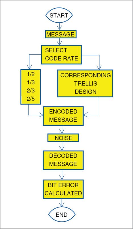
Block diagram of CC under different code rates, which are used in this application, is shown in Fig. 1. It illustrates the working of this project using MATLAB.

Software Program
The application program is developed in MATLAB version R2013a. It has a GUI for CCs under different code rates. To open a GUI panel of the command guide, type on the command window.
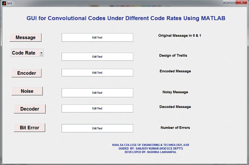
When bit1.m program is run, a screen will open up, prompting you to enter all the details. Key in the details in the GUI panel that appears on the screen, as shown in Fig. 2.

Steps
1. Press the different buttons as mentioned in the GUI. When the message button is pressed, input window will open, which means you need to enter a column size for random bit generation. Value of the column size can be any natural number of choice. By default, the value is ten.
2. After the message sequence is selected, message in the form of zeroes and ones is displayed on the screen. From the given code rates, you can select any code rate of your choice. This code rate will generate poly2trellis.
3. poly2trellis is used to accept the polynomial description of a convolutional encoder and return the corresponding trellis structure description. poly2trellis function includes constraint length and code generator.
Trellis = poly2trellis (constraint length, code generator)
4. Constraint length indicates the number of bits stored in the shift register, including the current bit. The code generator specifies the output connections for each encoder input bit stream.
Main parts of the GUI panel are shown in Fig. 2 and the description is given in the box.
5. The encoder will encode the message sequence and random noise will be added to the encoded message. At the decoder, the message is decoded using Viterbi algorithm.
6. At last, bit error is calculated, which indicates the number of errors in the decoded message sequence.
Steps for Testing
1. Copy the complete folder (update) of this project from the source folder or the website to your system.
2. Run bit.m program.
3. The main GUI panel for CC opens up on the screen (Fig. 2).
4. Click on Message button. Input window will open, which asks you to enter the column size of any random message.
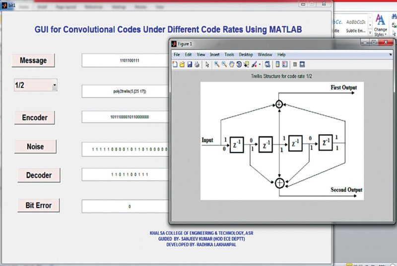
5. Select code rates out of the four defined. Select any one by pressing Code Rate button. Corresponding trellis design appears on the panel (Fig. 3).
6. Click on Encoder button to encode the message.
7. Click on Noise button to add random noise for inserting errors in the encoded message.
8. Here, the message is decoded by pressing Decoder button. Due to CC, errors inserted by noise are removed.
9. Finally, number of errors in the message is calculated by pressing Bit Error button.


Future Application
CCs are used to combat transmission errors caused by a noisy channel. These allow communication to achieve transmission reliability by reducing bit error rate. It reduces the amount of power needed for transmission of data.
Viterbi algorithm allows safe data transmission via error correction. Original message can recover accurately without any noise.
Download source folder
Sanjeev Kumar is head of department (ECE), Khalsa College of Engineering and Technology, Amritsar, Punjab


where is bit.m file ?
did you find the bit.m file
Bit.m file is under the Source folder. The link is given at the end of the article at “Download source folder”. The same can be downloaded from here http://efymag.com/admin/issuepdf/Error%20Correction%20Code%20Using%20Matlab.rar
Please guide us regarding the coding
that bit.m file only shows the front pannel but doesnt show the coding behind that pannel, it would be better if you show the methodlogy used in coding
The CODING BEHIND THE GUI SCREEN IS NOT VISIBLE AND THUS ITS HARD TO UNDERSTAND THE METHODOLOGY OF THE PROJECT.
hello
can anyone share the code of this project
the source file doesnt contain the bit.m file
if anyone can help it would be highly appreciated