Filters are an important part of electronic circuits today. Whether it is the analogue or digital world, the role of filters is very important. Presented here is a C++ program for an FIR filter design using the rectangular window technique.

However, before going deep into the designing of software for filters, it is necessary to understand the basic concept of filters. In both the analogue and digital worlds, the signal comes coupled with noise interruptions. To get rid of this unwanted noise, we use filters. Note that sometimes filters not only remove the unwanted signals but also some parts of the signal itself. For example, our speech signals have a bandwidth of 20 kHz but these are filtered up to 3.4 kHz without the loss of intelligence.
There are different types of filters available in the market:
Low-pass filter. This filter passes all the frequencies lower than a defined frequency (say f1 Hz) and rejects all other frequencies. Since it passes all the frequencies lower than f1 Hz, it is called a low-pass filter.
High-pass filter. This filter passes all the frequencies above f1 Hz and rejects all other frequencies. Since it passes all the frequencies above f1 Hz, it is called a high-pass filter.
Band-pass filter. This filter passes all the frequencies in between two frequencies, say, f1 and f2 and rejects all other frequencies. Since it passes a band of frequencies, it is called a band-pass filter.
Band-reject filter. This filter passes all the frequencies, except the ones falling between two frequencies f1 and f2. Since it rejects a band of frequencies, it is called a band-reject filter.
Application-wise, the filters discussed above have a very wide scope in the analogue domain. Let us focus on the design of filters in the digital domain, though functionality-wise the job of filters in both the domains remains the same.
In the digital world, there are two types of filters: FIR filters and IIR filters.
FIR filters. These filters are called finite impulse response filters. They are characterised by the impulse response given as:

where the impulse response H(z) is of finite length ‘N’ and x(n) is the input sequence.
IIR filters. These filters are called infinite impulse response filters. They are characterised by the impulse response given as:
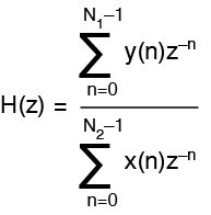
where the impulse response H(z) is infinite in duration.
FIR filters can be obtained using truncation of IIR response with suitable window functions. Here we make use of a rectangular window function given as w(n)=1. So the desired FIR is obtained as:

where hd(n) is an infinite-duration impulse response.
Software program
There are different methods of designing filters and so are the ways of implementing them. Here we have developed a ‘C++’-based software to design FIR filters using rectangular window method and obtain the frequency response of the same. The resultant software:
1. Displays a window with a list of various filters.
2. Prompts you to enter the filter type.
3. Allows you to choose the window length (N) up to 200.
4. Prompts you to enter the cut-off frequency in radians (user should enter the values between 0.2 and 2.6).
With this information, the software designed in C++ gives normalised filter response and actual filter response. Normalised filter response is designed to pass through the cut-off frequency of one radian. Actual filter response is designed to pass through a cut-off frequency specified by the user.
Also Read:Interesting Electronics Projects
Software structure. The program is developed using main.cpp, rec.h, graph.h and func.h files. The default path of the program is C:\TC\BIN\FIR\. The software is designed to follow the structure shown in Fig. 1.
The program files are described below:
main.cpp. This file contains the menu-driven program for user inputs.
func.h. It is a header file containing code related to rectangular window coefficients calculation.
rec.h. It is a header file containing code for supporting C++ graphics.
graph.h. It is a header file again to support graphic content in C++.
Output response. Now let’s run the program for different window lengths ‘N’ to observe the effect of ‘N’ on frequency response. The output frequency response is the graph of ‘N’ against the cut-off frequency (ω) expressed in radian per second. A normalised frequency scale is used.
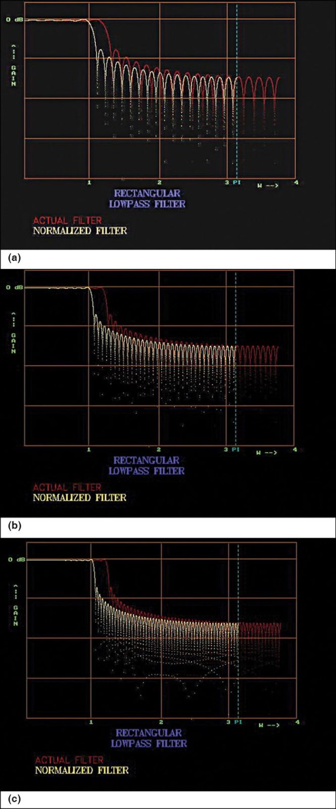
Low-pass filter. Simulation of the low-pass filter using a rectangular window is done by the software. Figs 2(a), (b) and (c) show the outputs of the low-pass filter at ω=1.0 for different rectangular window lengths (N) of 49, 99 and 149.
We will see frequency responses generated by the software for high-pass, band-pass and band-reject filters with various values of N and ω.
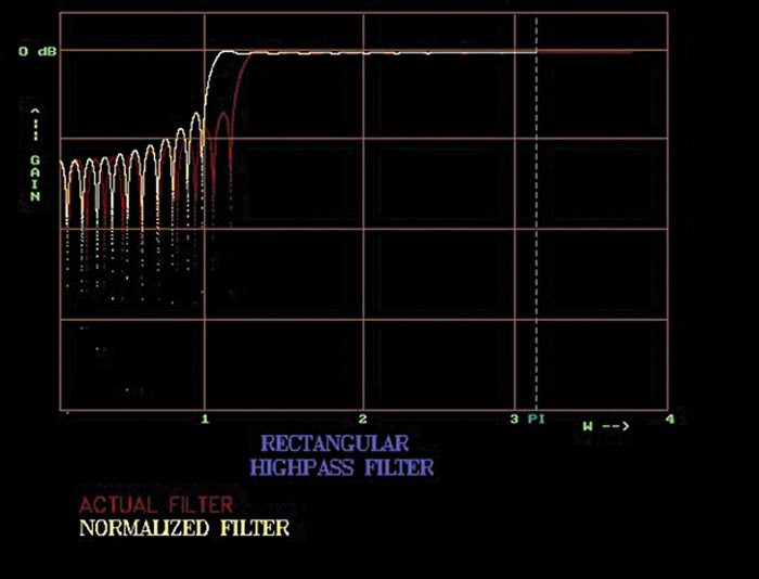
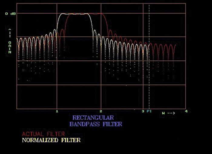
Frequency response of high-pass filter with N=61 and ω=1.2 is shown in Fig. 3. Frequency response of band-pass filter with N=61, ω1=1.2 and ω2=2.1 is shown in Fig. 4.
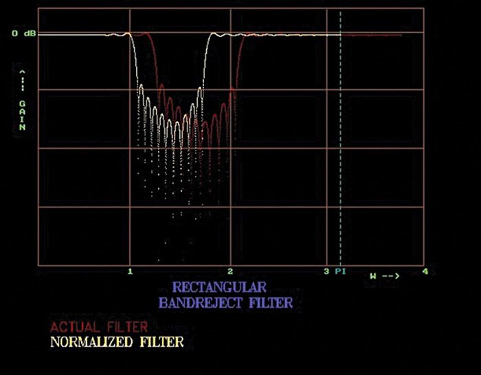
Frequency response of band-reject filter with N=91, ω1=1.2 and ω2=2.1 is shown in Fig. 5.
Download Source Code: click Here
Further, it may be observed that when ‘N’ increases, the width of the pass-band decreases and the slope of the transition band increases. The number of ripples increases in the pass-band with the amplitude of the end-ripple remaining the same, which however gets shifted towards the edge and finally out of the pass-band for larger values of ‘N.’ The width of the lobes decreases in the band-reject and the band-reject attenuation also increases with the increase in ‘N’ as more lobes enter the transition band. Moreover, the relative amplitude of the lobes remains constant.
Future applications
These filters can be used in a wide variety of applications like noise removal, selective passing of frequency contents in voice or any real-time waveforms. Using these filters’ sub-routine, you can design your own software for DSP applications or use this code to be translated in a hardware description language like Verilog or VHDL so it can be burnt into FPGA.
The author is an M. Tech from ABV-Indian Institute of Information Technology and Management, Gwalior, and B.Tech from Jamia Millia Islamia in New Delhi


