 Presented here is a linear-feedback shift register (LFSR) using Verilog that is designed and simulated using ModelSim testbench. Register-transfer level (RTL) models are quite popular in the industry as these can be easily synthesised using latest electronic design automation (EDA) tools. This project describes the RTL model of a synchronous circuit-an autonomous LFSR that executes concurrent transformations on a data path under the synchronising control of its input clock signal.
LFSR
Linear-feedback shift registers are commonly used in data-compression circuits implementing a signature analysis technique called cyclic-redundancy check (CRC).
Autonomous LFSRs are used in applications requiring pseudo-random binary numbers. It is a shift register whose input bit is a linear function of its previous state. The most commonly used linear function of a single bit is Exclusive OR (XOR). Thus an LFSR is most often a shift register whose input bit is driven by the XOR of some bits of the overall shift register.
There are numerous applications where LFSRs are used as pseudo-random numbers, pseudo-noise sequences and fast digital counters. Therefore hardware and software implementations of LFSRs are common.

Circuit and working
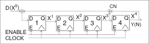
The sample block diagram of a 4-bit LFSR is shown in Fig. 1. An autonomous LFSR can be a random pattern generator providing stimulus patterns to a circuit. The response to these patterns can be compared to the circuit’s expected response and thereby reveal the presence of an internal fault. The autonomous LFSR shown in Fig. 1 has binary tap coefficients C1….CN that determine whether Y(N) is fed back to a given stage of the register. The block diagram shown here has CN =1 because Y[N] is connected directly to the input of the first stage.
An LFSR is basically a sequential shift register with a combinational feedback logic. Therefore it generates pseudo-random cycle sequence of binary values. Here, the LFSR loops through repetitive sequences of pseudo-random values.

Software program
The sample Verilog code (lfsr_tb.v.) is written for an eight-cell autonomous LFSR with a synchronous (edge-sensitive) cyclic behaviour using RTL design. Each bit of the register is assigned a value concurrently with the other bits; the order of the listed non-blocking assignments is of no consequence.
The movement of data through the register under simulation is shown in binary and hexadecimal formats. In this project, the register transfers up to eight bits (length=8) using the code:
//Verilog Source Code (lfsr_tb.v)
module Auto_LFSR_RTL(Y, Clock, Reset);
parameter Length=8;
parameter initial_state=8’h1001_0001;
parameter [1:Length] Tap_
coefficient=8’b1100_1111;
input Clock, Reset;
output [1:Length] Y;
reg [1:Length] Y;
always @ (posedge Clock)
if (reset ==0) Y <= initial_state; //
Active-low reset to initial state
else begin
Y[1] <= Y[8];
Y[2] <= Tap_Coefficient[7] ?
Y[1]^Y[8]:Y[1];
Y[3] <= Tap_Coefficient[6] ?
Y[2]^Y[8]:Y[2];
Y[4] <= Tap_Coefficient[5] ?
Y[3]^Y[8]:Y[3];
Y[5] <= Tap_Coefficient[7] ?
Y[4]^Y[8]:Y[4];
Y[6] <= Tap_Coefficient[7] ?
Y[5]^Y[8]:Y[5];
Y[7] <= Tap_Coefficient[7] ?
Y[6]^Y[8]:Y[6];
Y[8] <= Tap_Coefficient[1] ?
Y[7]^Y[8]:Y[7];
end
endmodule
The code for a 4-bit LFSR is:
//Verilog code (lfsr.v)
module lfsr (out, clk, rst);
output reg [3:0] out;
input clk, rst;
wire feedback;
assign feedback = ~(out[3] ^ out[2]);
always @(posedge clk, posedge rst)
begin
if (rst)
out = 4’b0;
else
out = {out[2:0],feedback};
end
endmodule
Testing and simulation
To simulate the LFSR design, install ModelSim V10.4a on a Windows PC and follow the steps given below:
1. Start ModelSim from the desktop; you will see ModelSim 10.4a dialogue window
2. Create a project by clicking ‘JumpStart’ in the welcome screen
3. In ‘Create Project’ window (Fig. 2), select a suitable name for your project. Set ‘Project Location’ and leave the rest as default, then click ‘Ok.’ ‘Add items to the Project’ window pops up (Fig. 3).

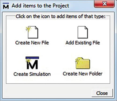
4. In ‘Add items to the Project’ window, select ‘Create New File’ option
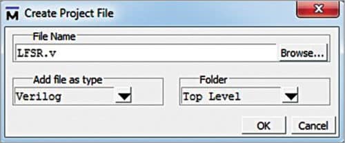
5. In ‘Create Project File’ window, give an appropriate file name (say, lfsr.v) for the file you want to add, and choose Verilog under ‘Add file as type’ and ‘Top Level’ under ‘Folder’ (Fig. 4)
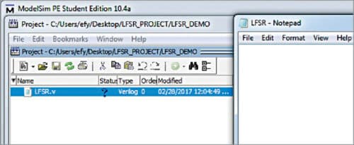
6. In the workspace section of the main window (Fig. 5), double-click the file you have just created (lfsr.v in our case)
7. Type your Verilog code in the new window. The main goal here is to write a self-test bench that will generate clock automatically for the simulation output window. Save your code from ‘File’ menu
8. Now, add the new file to lfsr.v by right-clicking it. Select Add to Project New File as shown in Fig. 6
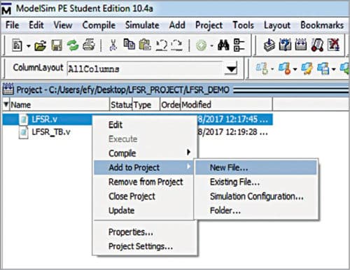
Give the file name as lfsr_tb.v. This is the test case where you can test and understand the working of a linear-feedback shift register. Details of this LFSR can be understood from the relevant source file.
Compiling/debugging project files.
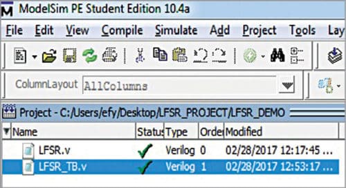
1. Select Compile Compile All
2. Compilation result is shown on the main window. A green tick against each file name indicates that there are no errors in the project (Fig. 7)
Simulating 4-bit LFSR.
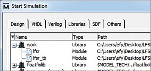
1. Select Simulate Start Simulation. Click ‘Library’ menu from the main window, followed by plus (+) sign next to the work library. You should see the name that you have just compiled in Fig. 7
2. In work library, select lfsr_tb and click ‘Ok’ (Fig. 8). This opens sim-Default window as shown in Fig. 9
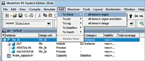
3. Go to Add To Wave All items in region
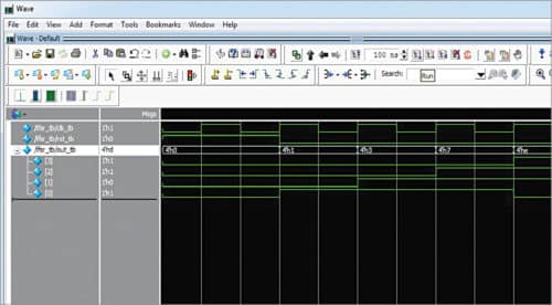
4. Monitor the LFSR for simulation purpose. The test bench is used to verify the LFSR for 4-bit mode. Now you are ready to simulate your design by clicking ‘Run’ from ‘Simulate’ menu bar as shown in Fig. 9. You can view the output on ‘Wave’ window as shown in Fig. 10.
Download source code
Feedback around an LFSR’s shift register comes from a selection of points (taps) in the register chain and constitutes XORing these taps to provide tap(s) back into the register. Register bits that do not need an input tap operate as a standard shift register. It is this feedback that causes the register to loop through repetitive sequences of a pseudo-random value. The choice of taps determines the number of values in a given sequence before the sequence repeats. The implemented LFSR uses a one-to-many structure, rather than a many-to-one structure, as this structure always has the shortest clock-to-clock delay path.