


 Presented here is a program to find the gain and DC offset values of an operational amplifier (or op-amp). While doing practical electronics experiments, especially in analogue electronics, we come across a very versatile component, that is, the op-amp. It is a low-cost single-chip solution to clumsy and difficult-to-troubleshoot multiple-transistors based designs.
A single op-amp can be interfaced to any sensor or transducer, and with proper biasing and power supply it may produce desired output signal levels. But op-amps, too, need external biasing with the use of minimal resistances and reference voltages.
Basically, a designer faces the challenges to set the gain and DC offset of the op-amp for producing the required output. There is a set of relationships that can be incorporated to find those required biasing components.

This software program does the work for you automatically by taking the required parameters from you, such as reference voltage, required output and input voltage swings. It then outputs a recommended design. You need to choose at least one component value by referring the datasheet of the op-amp to calculate the rest automatically. Then, you need to find the nearest component values to incorporate in the design.
To design such a circuit, there should be some known values that you need to feed as inputs in the program. For example, parameters like voltage level of a stable reference (Vref ), full-scale output voltage (Voutfs), zero-scale output voltage (Voutzs), full-scale input voltage (Vinfs) and zero-scale input voltage (Vinzs) are required.

Software
The software program is written using HTML, PHP and JavaScript, and can be incorporated in a system having PHP installed. It runs under PHP development environment. HTML is used as front-end software, whereas PHP is used as back-end software. JavaScript file checks for blank fields in HTML form.
PHP is incorporated in a Web server. So multiple user clients within the network can use this software simultaneously, like in a lab or college. The IDE used to develop this program is NetBeans, having PHP environment.
Three programs used in this project are opampRequirementForm.html, opampCircuit.php and opampDesign.js.
When you run opampRequirementForm.html, you get a window as shown in Fig. 1. This is the input form, where you need to enter all input parameters.
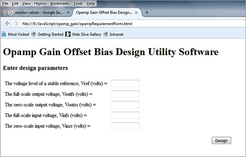
Fill all fields in the form in order to proceed to the next page, which is written in PHP, that is, opampCircuit.php.
The next page will show a recommended circuit design. This page also takes some inputs from you and calculates the required gain and offset values for circuit design by using the following relationship:
Gain=(Voutfs-Voutzs)/(Vinfs-Vinzs)
Offset=Voutzs – (Gain×Vinzs)
There will be four conditions, which are:
1. Positive gain and positive offset
2. Positive gain and negative offset
3. Negative gain and positive offset
4. Negative gain and negative offset
For positive gain and positive offset, output result of a typical example is shown in Fig. 2. Note the gain and offset values. Input parameters for this example are Vref =5, Voutfs=4,
Voutzs=3, Vinfs =2 and Vinzs=1.
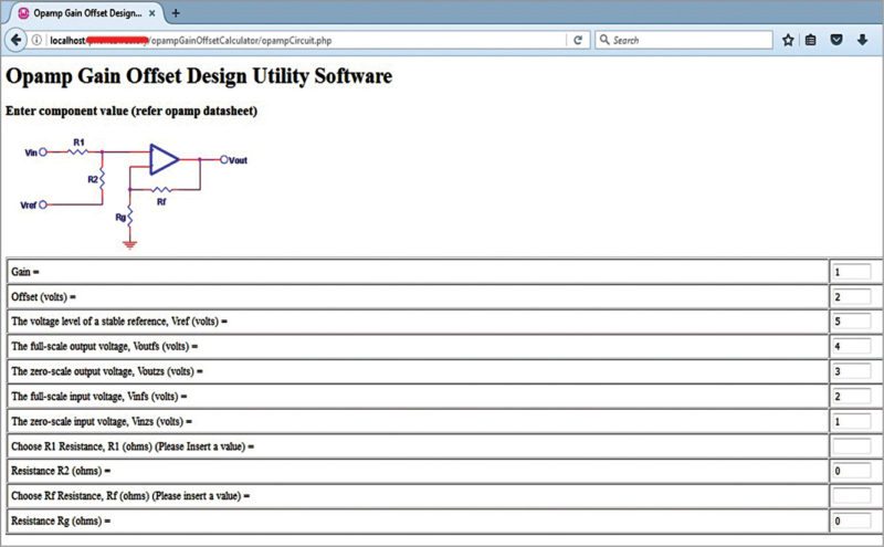
Since the gain and offset values are both positive, the condition satisfies. Consult the datasheet to choose suitable resistor values for R1 and Rf. As you enter these values, resistor values of R2 and Rg will change automatically. Find the nearest resistances to use in the actual circuit and check the results.
For positive gain and negative offset, a sample output is shown in Fig. 3. Note the gain and offset values. Input parameters for this example are Vref =5, Voutfs=2, Voutzs=-0.3, Vinfs =0.1 and Vinzs=0.05.
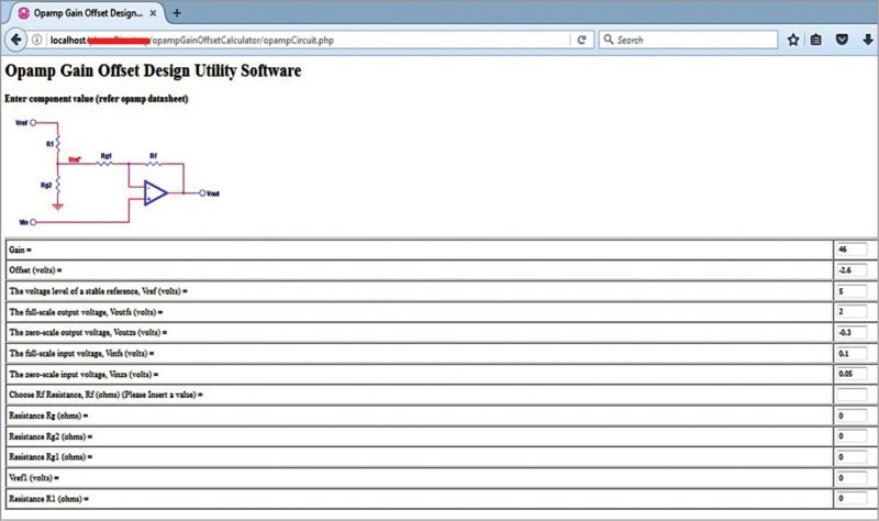
Here, you need to provide only suitable Rf value. Remaining values are automatically calculated for the circuit design.
For negative gain and positive offset, an example is shown in Fig. 4. Note the gain and offset values. Input parameters to be fed by you are Vref =5, Voutfs=4, Voutzs=5, Vinfs =-0.05 and Vinzs=-0.1.
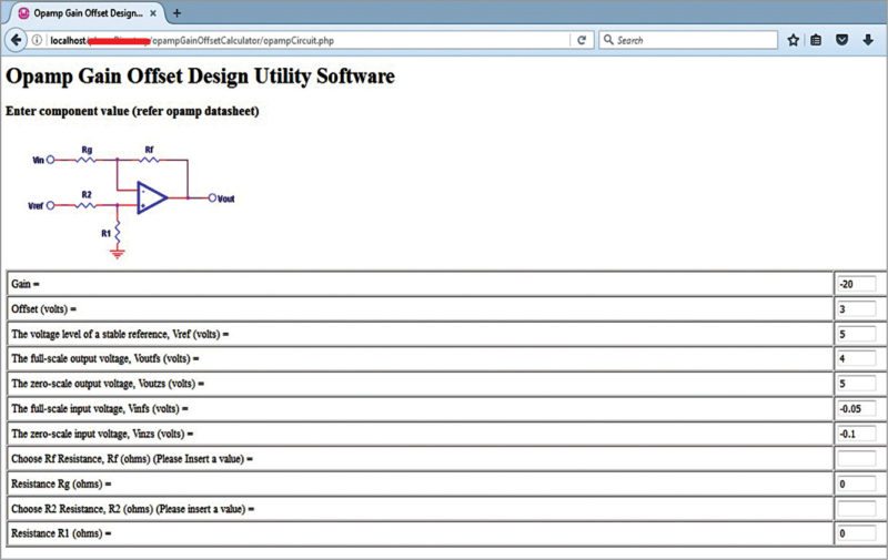
In this case, you have to enter suitable values for Rf and R2, and the rest are automatically calculated for the circuit design.
For negative gain and negative offset, an example is shown in Fig. 5. Input parameters are Vref =5, Voutfs=3, Voutzs=0.2,Vinfs =-0.2 and Vinzs=-0.1.
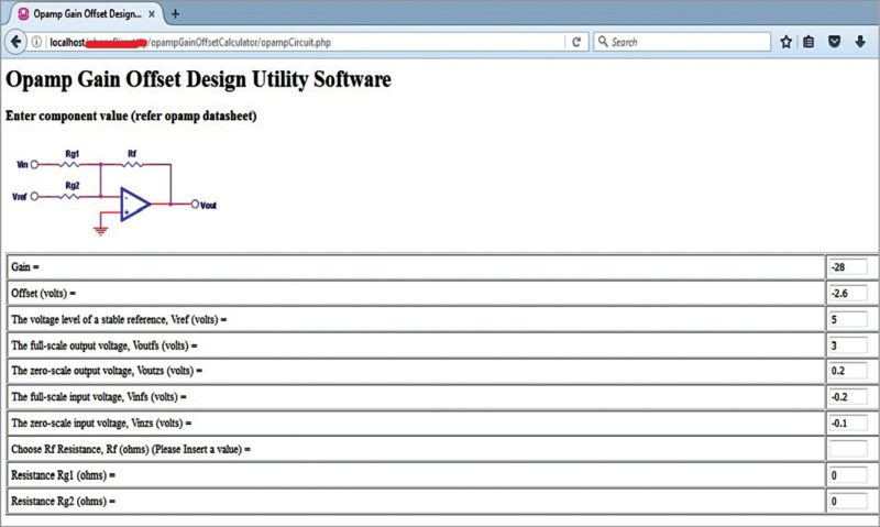
Here, enter the value for Rf to get suitable circuit design values.
All relationships are based on the basic op-amp theory of biasing component value calculations. Resistor values are in ohms and voltage values are in volts.
Benefit of this program is that it displays a recommended design. As a beginner, you can benefit from this program as it may provide hands-on calculations for all op-amp based experiments.
Software installation and testing
1. Download WampServer (for localhost development) from www.wampserver.com/en/ and NetBeans IDE from https://netbeans.org/features/php/. Install these in your Windows PC. WampServer version 2.5 and NetBeans version 8.1 were used during testing at EFY Lab.
Install appropriate Visual C++ extension (here VC++ 2012) before installing WampServer to get all prerequisite .dll files for smooth running of the IDE and Apache server environment.
2. WampServer runs in the background with the option in online mode. Make sure WampServer icon on the taskbar turns green.
3. Create a folder, say, op-amp under C:\wamp\www folder. Copy opampCircuit.php, opampDesign.js, and opampRequirementForm.html files including image files into the op-amp project folder.
4. Create a new PHP project in NetBeans. Select PHP Application option and click Next. A project folder will form automatically. Note that your op-amp folder is under this project folder.
5. Under Run Configuration window, make sure you select local server option in Run As: field; then, click OK to proceed.
6. Run opampRequirementForm.html file. You can feed various inputs as per your requirement and observe the outputs as shown in Figs 1 through 5.
Download source file
Ronie Adhiraaj Ghosh is M.Tech from Homi Bhaba National Institute, Mumbai. His hobbies include electronics projects, watch collection, camping and hiking
