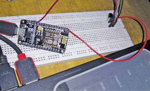
 This temperature monitoring system is based on Cayenne Internet of Things (IoT) platform, NodeMCU microcontroller (MCU) and Message Queuing Telemetry Transport (MQTT) protocol. The authors’ prototype is shown in Fig. 1.
Cayenne IoT Platform accelerates the development of IoT-based solutions, including quick design, prototyping and other commercialised projects. It is a drag-and-drop IoT project builder that can help developers build complete, ready-to-use IoT solutions with little to no coding.
Cayenne IoT Platform contains a vast catalogue of certified IoT-ready devices and connectivity options. This allows users to easily add any device to the library utilising MQTT API. All devices in Cayenne are interoperable and benefit from features such as rules engine, asset tracking, remote monitoring and control, and tools to visualise real-time and historical data.
MQTT is a lightweight messaging protocol for sensors and mobile devices.
Circuit and working
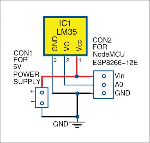
The circuit diagram of the temperature monitoring system is shown in Fig. 2. Hardware used in the project include NodeMCU (ESP8266-12E), temperature sensor (LM35) and 5V power supply.
NodeMCU
NodeMCU ESP8266-12E MCU is a development board with one analogue and many general-purpose input output (GPIO) pins. It has 4MB flash memory, and can operate at a default clock frequency of 80MHz. In this project, analogue pin A0 of NodeMCU is used to read output voltage of LM35 temperature sensor.
LM35
This is a precision IC temperature sensor. It provides output voltage that is linearly-proportional to temperature (in °C). It exhibits typical accuracies of ±1⁄4°C at room temperature and ±3⁄4°C over a full temperature range from −55 to +150°C.
LM35 provides sensitivity of 10mV/°C. In this project, Vout pin (pin no. 2) of LM35 is connected to pin A0 of NodeMCU. Pins 1 and 3 of LM35 are connected to +5V and Gnd, respectively.
NodeMCU programming with Arduino IDE
You need Arduino IDE software to program NodeMCU. Download the latest Arduino IDE from the website and install it on your computer.
Steps for adding NodeMCU ESP8266 board and library to Arduino IDE are given below.
- Open Arduino IDE. Go to File menu and select Preferences.
- Copy this package and paste in Additional Boards Manager URL.
- Go to Tools and select Boards Manager.
- Type esp8266 in search box and press Enter.
- Install the latest version.
- From Tools menu, select NodeMCU 1.0 (ESP-12E module) board.
- Select Include Library from Sketch menu.
- Download the library from this link.
- Click on Add ZIP Library and add Cayenne-MQTT-ESP-master zip file, or directly copy the folder (Cayenne-MQTT-ESP-master) and paste it in Libraries folder of Arduino IDE.
Software
The source code (cayenne_sensor.ino) to program NodeMCU is written in Arduino programming language. ESP8266-12E is programmed using Arduino IDE software. Open Arduino IDE and select the correct board from Tools®Board menu in Arduino IDE.
The source code starts with #define CAYENNE_PRINT Serial and #include <CayenneMQTTESP8266.h>
Here, CayenneMQTTESP8266.h header file is used to interface NodeMCU with https://cayenne.mydevices.com
Cayenne.begin( ) is used to connect Wi-Fi and Cayenne dashboard with Nodemcu.
Cayenne_out_default() and Cayenne.virtualWrite(1,a) are used for writing sensor data (‘a’) on channel number 1.
Serial.begin(9600) function initialises the serial port with a baud rate of 9600.
Enter your Wi-Fi name and password in the source code, as indicated by xxxxx below. Also provide other details in the source code, such as username, password and client ID obtained from Cayenne as explained in the next section.
#define CAYENNE_PRINT Serial
#include <CayenneMQTTESP8266.h>
// WiFi network info.
char ssid[] = “xxxxx”; //put your own ssid
char wifiPassword[] = “xxxxx”; //put your
wifi password
// Cayenne authentication info. This should
be obtained from the Cayenne Dashboard.
char username[] = “xxxxx”;
char password[] = “xxxxx”;
char clientID[] = “xxxx”;
After adding all details in the code, compile it and upload the program (sketch) using a standard USB cable to NodeMCU.
Download Source Folder
Hardware interfacing with Cayenne IoT platform
To interface the circuit with the IoT platform, open this link on any browser. Click on Sign Up Free (Fig. 3). Fill all the fields and click on Get Started Free.

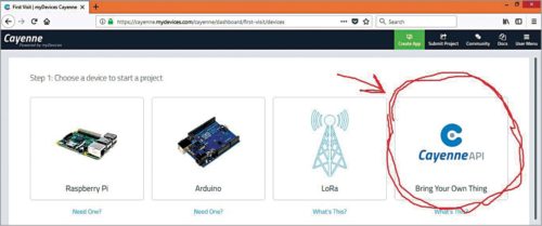
Next, click on Bring Your Own Things (Fig. 4) from Cayenne API.
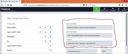
Copy MQTT username, password and client ID from Create App (Fig. 5). Paste these respective details under username, password and client ID in Arduino source code (cayenne_sensor.ino), along with your Wi-Fi name and password.
After successfully compiling and uploading the code to NodeMCU, open Serial Monitor in Arduino IDE. You will see ESP8266 connected to Wi-Fi. After the connection is established, the previous page is automatically updated on Cayenne. A new dashboard opens in the browser. Cayenne generates an ID and a device icon for your device (Fig. 6)—you may change it in Settings.
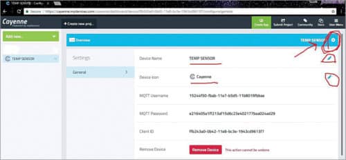
Click on Add new and then Device/Widget in Settings (Fig. 7).
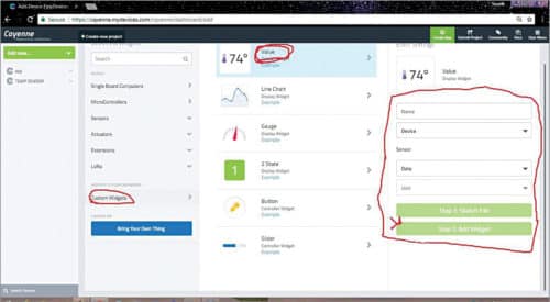
Click on Custom Widgets and then value, and populate all fields (Fig. 8). The channel number should be 1. (Make sure the channel number is same as in code.) Now, click on Add Widget.

When a connection is made, sensor data gets uploaded to Cayenne. Temperature data on Cayenne is shown in Fig. 9.
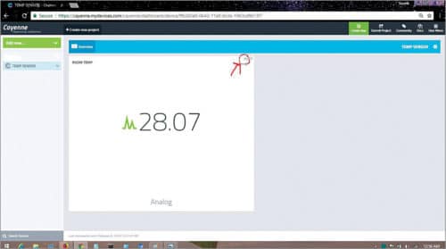
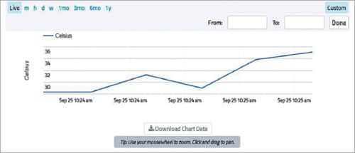
You can get a graphical representation of temperature data by clicking on the encircled icon shown in Fig. 10.
You can also download Cayenne Android app by myDevices from Google Play Store. The rest of the procedure is the same for accessing temperature data on your smartphone.
Souvik Kumar Das is passionate about electronics and MCU-based system design
Shibendu Mahata is M.Tech (gold medalist) in instrumentation and electronics engineering from Jadavpur University. He has written in the domain of signal processing in many reputed international journals


