


 A simple circuit of a solar lamp with variable power supply and charger is described here. It is useful where mains power failure is frequent. The power supply can be used for testing electronics projects and also charging your mobile phone battery. You can save on your electricity bills by switching to an alternative source of power using this circuit. The circuit works with the solar panel (without mains power supply) and can be used as a solar lamp during daytime (with the solar panel), night lamp (with external 12V battery), variable power supply (1.5V to 15V) and mobile battery (3.6V) charger.
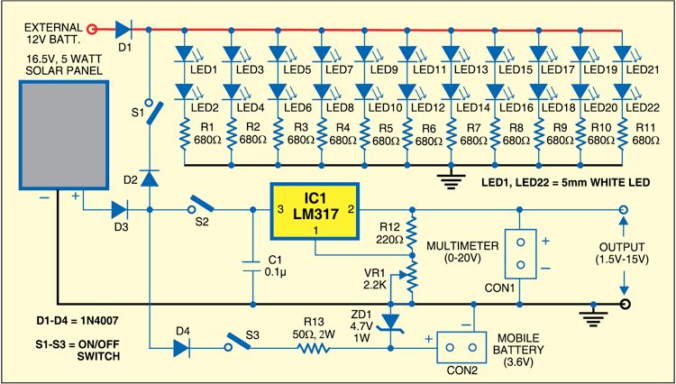
The photovoltaic module or solar panel used here is capable of delivering a power of 5 watts. In full sunlight, it outputs 16.5V. The solar panel can deliver a current of 300-350 mA. Using it you can charge Li-ion batteries common in mobile phones.
Working of the Solar Lamp Circuit
The working of the circuit is simple. The output of the solar panel is fed to the circuit via diode 1N4007 (D3), which acts as a polarity guard to protect the solar panel.

For using the small LED-based lamp in daytime, just flip switch S1 to ‘on’ position. All the 5mm white LEDs (LED1 through LED22) glow. To get a higher light intensity, you can use a reflector. Similarly, if you want to use the lamp at night, connect a 12V battery to the anode of diode D1.
For using the variable power supply, flip switch S2 to ‘on’ position. Connect a multimeter across CON1 terminals and set the required voltage (say, 9V) using potmeter VR1. The 9V output will be available across CON1 terminals. As mentioned earlier, the range of the power supply is 1.5V to 15V.

For charging a Li-ion battery (used in mobile phones), flip switch S3 to ‘on’ position and use connector CON2. Zener diode ZD1 provides 4.7V to charge the Li-ion battery. Using this circuit, you can charge a 3.6V Li-ion cell very easily. Resistor R13 limits the charging current.
Assemble the circuit on a general-purpose PCB and enclose in a small box. Mount RCA socket on the front panel of the box. Use RCA plug with cable for connecting the battery and LEDs. Also mount all the switches on the front panel of the cabinet.
