


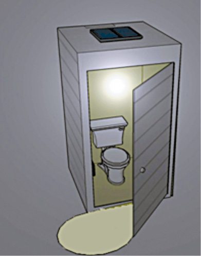
 Despite being more expensive than standard permanent outdoor toilets, portable toilets (Fig. 1) have several significant benefits as these are self-contained and can be placed almost anywhere. These days portable toilets are frequently seen at outdoor areas like construction sites, farms, campsites and even street-sides. Solar power provides an ideal solution for applications where lighting is required in portable toilets that are located away from a mains supply grid, or the installation is expected to be on the site for a brief period.
Here is a circuit of a self-contained solar light for portable toilet lighting applications. The solar light housed within its own enclosure comprises a solar charger, rechargeable battery pack, white LED light source and PIR motion sensor as an occupancy sensor. The occupancy sensor (motion sensor) activates the light source and, after the booth has been vacated (or when there is no valid motion), the lighting switches off to save battery.
Circuit and working
Circuit diagram of the solar light for a portable toilet is shown in Fig. 2. It is built around a 9V, 450mA solar panel, voltage regulator LM317 (IC1), a PIR sensor, MOSFET BS170 (T1), a 1W white LED (LED1) and a few other components.

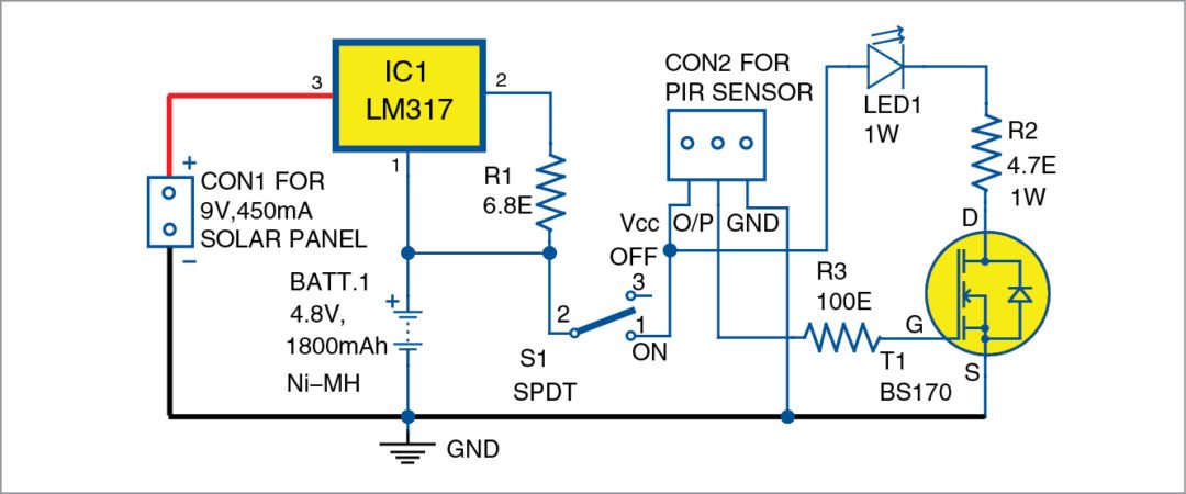
The circuit may be split into two sections: the charger and the sensing and control system. Power is supplied via the 9V, 450mA-rated polycrystalline solar panel, which is linked to CON1 and charges the 4.8V, 1800mAh battery pack, BATT.1, via the constant-current charger built around IC1. The 6.8-ohm resistor (R1) limits the charging current to near one-tenth rate of the battery, that is, 180mA.

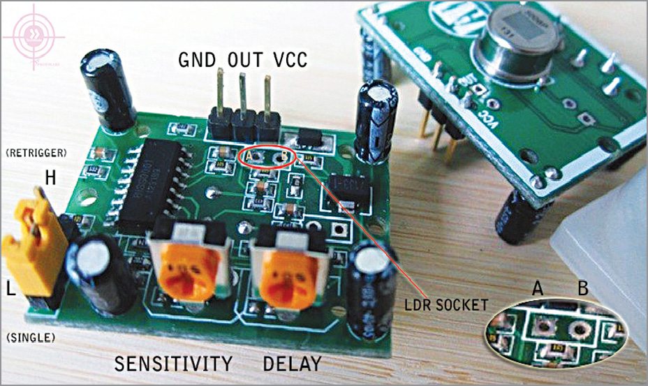
The sensing and control circuitry is based on PIR motion detector module (Fig. 3), which is connected across CON2. When a valid motion is detected, output of the PIR sensor goes to around 3.3V and the light source LED1 (3.6V, 1W white LED) is switched on through medium-power MOSFET BS170 for a finite time. The 4.7-ohm, 1W resistor R2 limits the operating current of the white LED.
Construction and testing
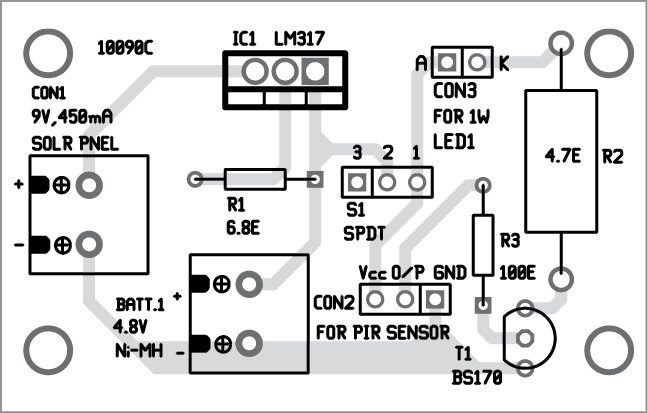
A PCB for the solar light for a portable toilet is shown in Fig. 4 and its component layout in Fig. 5. Enclose the PCB in a suitable small box in such a way that it can be fitted in the toilet.
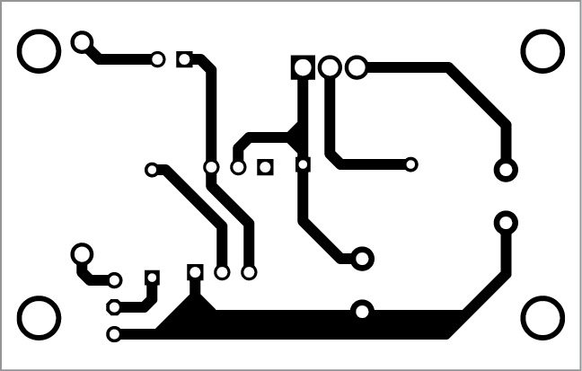
Download PCB and component layout PDFs: click here
After assembling the PCB board, connect the fully-charged battery pack BATT.1 to the circuit and switch on S1. The PIR motion sensor detector requires an initialisation time of about 60 seconds (or even up to three minutes). Thereafter, it enters standby mode, ready for detection.
You can adjust the delay potmeter in PIR sensor clockwise to increase the time delay from three seconds to up to 300 seconds. Similarly, turning the sensitivity pot in PIR sensor clockwise increases the detection sensitivity from three to six metres. In some PIR sensor potmeters, the LDR socket option is not provided.
The solar panel (not fitted within the enclosure) can be mounted at an appropriate location. Battery pack BATT.1 is best linked to the circuit via two flexible, well-insulated multi-strand wires. Then, a heat-sink should be added to IC LM317.
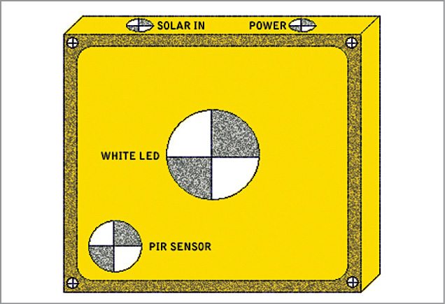
Finally, house the assembled PCB in a small plastic case with holes drilled for the connectors for linking the solar panel, switch S1, LED1 and PIR motion sensor. The suggested enclosure is shown in Fig. 6.
EFY Note
Connect LED1 externally, with a proper heat-sink, to CON3 in the PCB.
T.K. Hareendran is an electronics hobbyist, freelance technical writer and circuit designer

I would like to understand why the LM317 GND is connected to the battery and how is affecting the charging behavior, because the R1 is for charging the battery, but the GND Pin of LM317 is connected to the battery Plus.
Prov94, thinking of pin-1 as “GND” is actually wrong. It is truly a voltage adjust (reference) pin. As such, and due to an internal zener diode, the output voltage will always be 1.25v higher than whatever the voltage is on this adjust pin-1 . It is this property which permits this adjustable regulator to also act as a current source. The 1.25v across the 6.8 ohm resistor causes around 180mA to flow. This current passes through the battery to the actual circuit GND return back to the source: the solar cell. This rather old device has many properties which make it quite useful in a variety of ways even today.
https://i.stack.imgur.com/JYNOm.png
Hi
It is very good for me
thanks
sent me more please
The idea was wonderful, this may save up a lot of energy and won’t be needing any electricity especially when u were in the field. Great idea you share here!
Thank you for your feedack.