


 Generally, solar panels are stationary and do not follow the movement of the sun. Here is a solar tracker system that tracks the sun’s movement across the sky and tries to maintain the solar panel perpendicular to the sun’s rays, ensuring that the maximum amount of sunlight is incident on the panel throughout the day. The solar tracking system starts following the sun right from dawn, throughout the day till evening, and starts all over again from the dawn next day.
Solar tracking system circuit
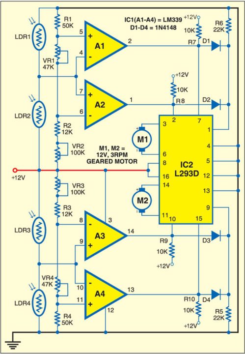
Fig. 1 shows the circuit of the solar tracking system. The solar tracker comprises comparator IC LM339, H-bridge motor driver IC L293D (IC2) and a few discrete components. Light-dependent resistors LDR1 through LDR4 are used as sensors to detect the panel’s position relative to the sun. These provide the signal to motor driver IC2 to move the solar panel in the sun’s direction. LDR1 and LDR2 are fixed at the edges of the solar panel along the X axis, and connected to comparators A1 and A2, respectively. Presets VR1 and VR2 are set to get low comparator output at pins 2 and 1 of comparators A1 and A2, respectively, so as to stop motor M1 when the sun’s rays are perpendicular to the solar panel.
Circuit operation
When LDR2 receives more light than LDR1, it offers lower resistance than LDR1, providing a high input to comparators A1 and A2 at pins 4 and 7, respectively. As a result, output pin 1 of comparator A2 goes high to rotate motor M1 in one direction (say, anti-clockwise) and turn the solar panel.

When LDR1 receives more light than LDR2, it offers lower resistance than LDR2, giving a low input to comparators A1 and A2 at pins 4 and 7, respectively. As the voltage at pin 5 of comparator A1 is now higher than the voltage at its pin 4, its output pin 2 goes high. As a result, motor M1 rotates in the opposite direction (say, clock-wise) and the solar panel turns.
Similarly, LDR3 and LDR4 track the sun along Y axis. Fig. 2 shows the proposed assembly for the solar tracking system.
WHAT SHOULD BE THE RATING OF LDR
LDR is cheap, it costs 2 to 5 rupeer.
desejava o desenho do circuito impresso para este seguidor solar
Desculpe, atualmente não temos o layout impresso para este circuito em particular, pois é apenas um protótipo.
where did solar panel connect . clear connection can u plz send to me
Solar panel doesn’t connect to the circuit. It connects to your charge controller. This connects to the battery or controller output at the 12v and ground rails.
What are VR1 and VR2 and VR3 and VR4? i have used 9V motor and 9V battery, do i need to change the resistances?
Did the circuit worked?
VR1, VR2, VR3 and VR4 are variable resistors or presets.
what are vr1,vr2,vr3 and vr4?
what are the significances of vr1 in the circuit?
if we are using 9v battery and motor then do we need to change the value of the resistances?
They are variable resistors. VR1 is used to set the voltage at output pin2 of comparator (A1). You may use 9V battery as power supply but in that case the output level at each comparator output will be different. And also you need to recalibrate the resistances at the input of each comparator.
How is it that data sheet for L293 shows VCC1 must be less than 7v
This circuit will destroy L293
No. Look carefully, the input voltage goes thru a 10k resistor so the voltage at those pins will be less or around 7V. The supply voltage may go up to 36V but in this case, only 12V is supplied. This circuit is based on a DIP package and NOT the SO package. If you use SO package, change the pinouts to reflect with the datasheet.
The circuit is not working…
Kindly elaborate your query.
I need pcb layout for this circuit.. can u plz provide??
Dear Mr. Sunil Kumar.
I have made your circuit. I have had many problems.
The Moto 2 never worked.
In the end, the best solution was to add another IC LM339 and repeat the components and configuration of pins 1 to 7 for Motor 1 in the second IC LM339.
Please, you can verify the circuit. From already thank you very much.
i need to do the solar tracking system project work can you send me all the necessary ….
Am interested in this project can you please send me more details
what is the function of these 4 diodes?
I need more details on this pls
[email protected]
Kindly elaborate your query.
Will the LDRs not get fried or bridge the power supply if they are fully illuminated equally under bright sunlight?
Worked well. But will the LDRs not get fried or bridge the power supply if they are fully illuminated equally under bright sunlight?
Thanks for the feedback!. No, LDRs with the operating temperature upto 80 degree centigrade are easily available in the market.
I need more details on this pls
send on
[email protected]
proteus l293d have 14 pins. How will the proteus link?
Comment:I need more details on this solar circuit.
hi sir, is it possible for u to send me detail abt this project?
Hi Nabin, all the information are present in the article.
i am trying to inter face the the motor with l293d and i am trying to run the motors in opposite directions
but the motor is running in same direction please help me with code.
I’ve some doubts, can I contact you through mail
You can contact me at [email protected].
what is the specs for the D! to D4 diodes ? 12 volt?
really nice article it helped us in making project in my college, but we made it without programming
Hi, thanks for the circuit, I have it on a bread board but if Ldr1 gets more light, M1 turns counter clockwise, if Ldr2 gets more light, nothing happens. If I ajust Vr2, then Ldr2 gets more light, M1 still turns counter clockwise. All is the same with Ldr3, Ldr4, Vr3 and M2 except M2 always turns clockwise. What does L293 reverse the polarity at pins 3 and 6, I haven’t seen that happen yet. Thanks for checking this out!
I could ask you for more information
[email protected]
You can mail all your queries to [email protected]
Hi EFY team.
I appreciate your work. Would you please send me the PCB. Will this circuit return the solar panel to dawn time position at end of the day?
Please how do you stop the motor from rotating when it has gotten to its set point?
and how do you control the speed at which the motor turns?
where can i get the components
I just came across this wonderful article.
I wonder if you have a calibration process you can give me? I’m speaking about how to set VR1, VR2, VR3, and VR4.
Do you have the specification for the LDRs? Or part numbers?
Should I use two separate 12 volts sources, one for the +12 volts on pins 8 and 16 of L293D, and a second one for the +12 volts for the comparators and pins 2, 7, 10, and 15 of the L293D?
I assume the motors are reversible, correct? Can you please give me the specification for the motors?
Many thanks for your kind assistance.
I am not getting voltage from L293 motor outputs. I wonder if anyone has run the circuit, I need your comments.