 The basic function of a relay is to switch on power to a load using an electrically isolated, low-power control signal. Hitherto, electromechanical relays have been the components of choice to perform this function. The advances made in semiconductor technology have resulted in the emergence of a solid-state relay.
Recommended: We have recently developed an AC touch-controlled solid-state relay (SSR) capable of handling input voltages ranging from 100V to 250V AC.
Solid-state relay circuit

Solid-state relays provide the advantages of almost infinite switching, bounce-free operation, immunity to electromagnetic interference (EMI), higher operating speeds, low-voltage control, small package size and multifunction integration.
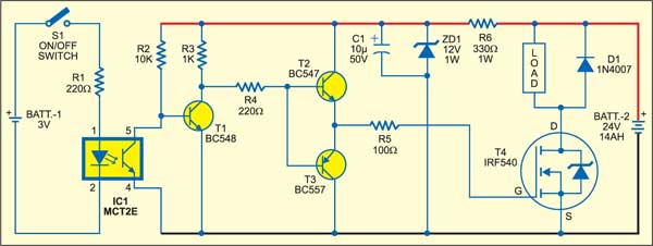
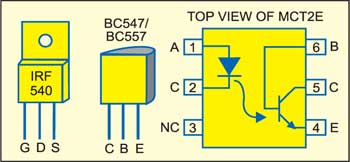
Here we describe a DC operated solid-state relay that uses readily available components (see Fig. 1). It operates off a 3V DC battery or TTL compatible PWM input. Pin configurations of MOSFET IRF540, transistor BC547/BC557 and opto-coupler are shown in Fig. 2.

The load voltage may be supplied by an automobile or tubular battery of voltage anywhere between 24V and 96V for driving up to 10A current through the load. Here we have used a 24V DC battery. The value of series resistor R6 (330 ohms) will change depending on the battery voltage to supply 30-35mA current. The value of resistor R6 can be calculated as:
R6 = 1000 x (Bat.2 V–12V)/35 and its power dissipation=(35/1000)2 x R = 0.001225R
Note
The wattage of R6 should be at least twice its power dissipation.
When S1 is pressed, the opto-coupler input is high (logic 1) and the MOSFET triggers to activate the load. When S1 is open, the opto-coupler input is low (logic 0) and the MOSFET doesn’t trigger. As a result, the load remains inactivated.
The article was first published in April 2006 and has recently been updated.


can we use load voltage 220 V DC?. what should be change to use 220 V DC?
R6 = 1000 x (Bat.2 V–12V)/35 and its power dissipation=(35/1000)2 x R = 0.001225R