 In movies like Ironman and Players, it is shown that appliances are operated by human speech or sound. Similar concept of a sound operated device control system implemented in this project. The system responds to pre-stored sound and performs particular functions. That is, command signals are first stored in the database and when you run the project, a real-time sound or speech signal is compared with the signals stored in the database. If signals match, an appliance/load is turned on/off. For instance, sound command ‘Switch on the fan’ is used to operate the fan.
This project has vital applications especially for the differently abled and can also be used to provide security and authentication.
Sound operated device control system block diagram
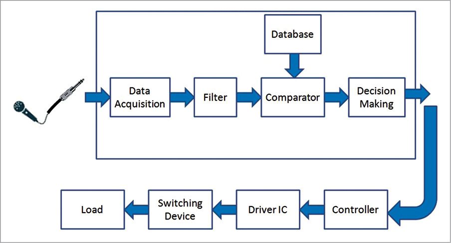
The project can be developed by various methods using different algorithms like biometrics, fuzzy logic, neural networks and hidden Markov. The easiest and most efficient method is cross-correlation algorithm implemented by LabVIEW software. Fig. 1 shows the block diagram of the project with connections between different modules. Various processes like speech acquisition, speech filtering, speech comparison and decision making are easy to program in LabVIEW because of its user-friendly graphical programming environment.
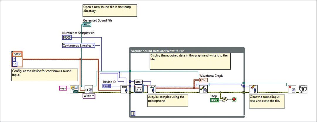
A predefined command is stored in the system. With the help of a microphone, real-time sound signal is acquired by LabVIEW functional block. This acquired sound is not suitable for cross-correlation or comparison because of the noise within the real-time speech.
So it is advisable to filter the acquired signal using low-pass Butterworth filter to remove unwanted frequencies or noises. Low-pass Butterworth filter gives flat frequency response.
Output of the filter is given to the cross-correlation block to compare this signal with pre-stored command. We have used AT89S51 as controller.
The project includes the following programs: Wav file Creation Sub VI.vi, Cross Corelation.vi, Serial Communication.vi for front end LabVIEW program and Voice.c for the AT89S51 microcontroller.
Functionality of the virtual instrument
Acquisition of audio file. Acquired real-time sound command is stored in wav file format.
Creation of wav file in LabVIEW can be done with the help of Virtual Instrument or VI, shown in Fig. 2. Filter parameters are configured by setting low-pass Butterworth filter as cut-off frequency 3000Hz and filter order 4. Device ID is set as ‘0’ for one-input device. Remaining block parameters are taken as by default.
Wave file creation VI creates or records wav file from audio command given by the user. The wav file is stored automatically on the default path. The path is shown on the label named ‘Generated File Path’ in the front panel of VI. The first-time generated wav file should be used as reference wav file or library wav file for comparison. Command should be something like ‘Switch on the fan.’
Path generated in the front panel for library purpose should be given to the next VI (cross-correlation) at label named Library command. For storing command, click Run on the block diagram of VI. The command should be at least of four seconds with at least one second between words of command. You can store or give audio command using a headphone or directly from the inbuilt microphone of the laptop. Library command should be stored in noise-free environment.
Cross-correlation VI
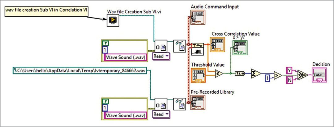
The wav file creation VI is kept in 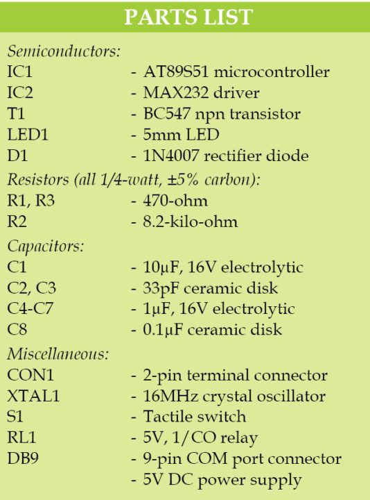 cross-correlation VI as sub-VI (VI within the VI) as shown in Fig. 3. Two different audio wav files are compared using 1D cross-correlation function block. Cross-correlation is a mathematical tool to analyse any function or continuous signal.
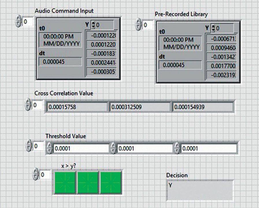
If both files are the same, then correlation value should be between 0 and 1 (value can be between 0.0001 to 0.67). In case of unmatched speech command, obtained value is in between 0.1E-5 and 0.9E-5. On the basis of this, threshold value is set as 0.0001. By setting very accurate threshold value, this project can be used for security and authentication purposes.
This VI will compare library file (audio command stored) and run-time command given by user. It needs a threshold value for comparison. So enter appropriate threshold value at the label named ‘Threshold Value’ in the front panel (Fig. 4). Threshold value should be between 0.0001 and 0.0005 using trial-and-error method.
Serial input output VI
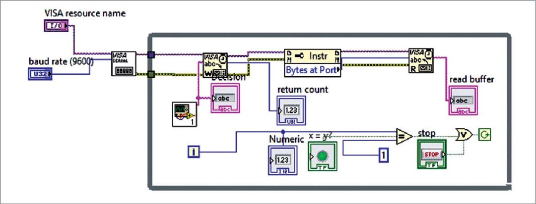
Decision ‘Y’ or ‘yes’ (Boolean 1) is generated if output of comparison is greater than threshold value, else ‘N’ or ‘no’ (Boolean 0) is generated. ‘Y’ or ‘N’ output is transmitted to AT89S51 controller via serial communication VI (Fig. 5), which is configured as frame bits 8, baud rate 9600, parity and flow control none. Cross-correlation VI is a sub VI of serial communication VI.
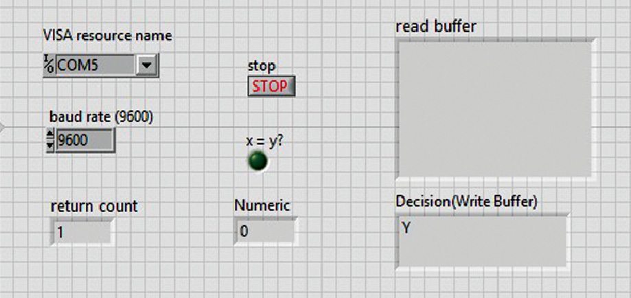
Before running serial communication VI, attach USB-to-serial communication cable to the laptop. This cable is detected at the label named ‘Visa Source Name’ as shown in the front panel (Fig. 6). After running this VI, other first two VIs automatically run in the background. Now, give run-time command to the device you want to turn on or off.
Sound operated device control system hardware
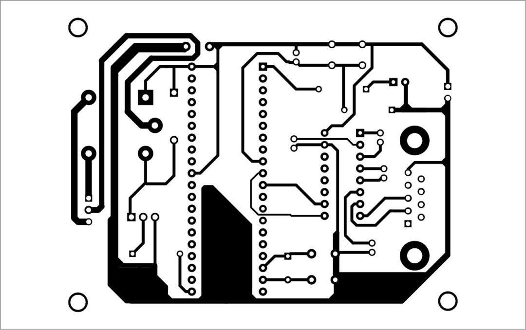
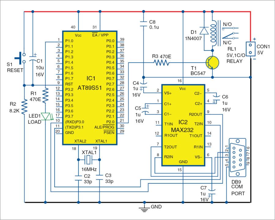
Fig. 7 shows the circuit diagram of the sound-operated control system. AT89S51 microcontroller is the heart of the system. Output from LabVIEW is given to the controller using USB-to-serial communication cable (DB9 connector). Output command of VI, for instance, ‘yes’ or ‘no’, is given to the controller in terms of ASCII.
The controller is programmed as follows: If received ASCII value from LabVIEW is ‘yes,’ a relay (RL1) should operate and for ‘no’ ASCII value, relay should not operate. Device/load is switched on or off through relay RL1.
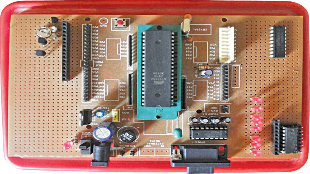
Author’s prototype is shown in Fig. 8. The same can also be implemented on Arduino board. Code for Arduino is also included in this project.
Construction and testing
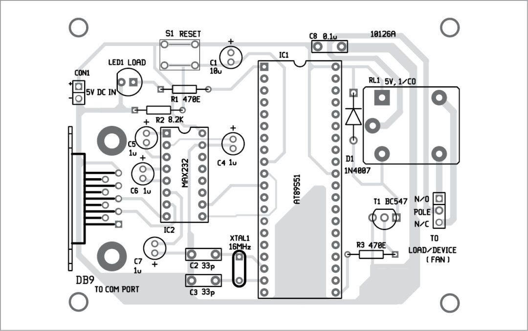
A singleside PCB pattern of the sound-operated device-control system is shown in Fig. 9 and its component layout in Fig. 10. After mounting all components on the PCB, connect the serial cable from DB9 connector to COM port of your PC. Also, connect the load across RL1.
Run LabVIEW program. First, select appropriate COM port from LabVIEW front panel and record your voice by clicking on the wav file creating VI and sub VI as shown in Figs 2 and 3.
Run-time voice command is compared with the recorded voice command and output is generated as ‘Y’ if voice command matches and ‘N’ if voice command does not match. If ‘Y’ signal is received in AT89S51, RL1 is energised and the load is turned on. Make sure that the threshold value in cross correlation.vi is 1E-8.
Download PCB and Component Layout PDFs: Click here
Downlod the source code: Click here
Feel interested? Check out other electronics projects.


source code file contains the PCB layout.
Thank you Arpita, the article has been updated with the original source code.
Hi, can i do this project using arduino?
Thank you Dara,
You can not use Arduino as this is based
on AT89S51 and LabVIEW.