 This sound operated timer is based on LM324 quad-operational amplifier and NE555 timer. Time delay can be set from a few seconds to 30 minutes. It can also be used as a sound sensitive burglar alarm.
Sound Operated Timer Circuit and Working
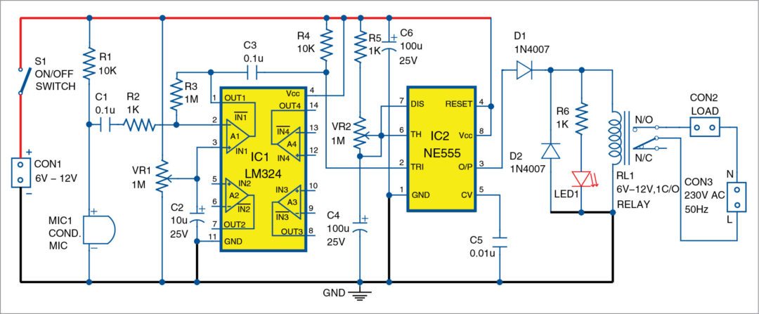
Circuit diagram of the sound operated timer is shown in Fig. 1. Output pin 1 of LM324 (IC1) is fed to pin 2 of NE555 (IC2) through capacitor C3. IC2 is configured as a monostable multivibrator. Sound signal, like clapping, sensed by condenser microphone MIC1 is amplified by IC1.

Amplified signal is fed to trigger pin 2 of IC2. Output pin 3 of IC2 goes high and relay RL1 gets energised for a time delay set by potmeter VR2. Time delay can be set from a few seconds to 30 minutes. Energisation of the relay is indicated by the glowing of LED1.
Relay RL1 is de-energised after the time delay. NE555 can source 200mA current; so, an ordinary relay can be directly connected to IC2’s output without an extra transistor driver. Use a good-quality microphone for maximum sensitivity.
Construction and Testing
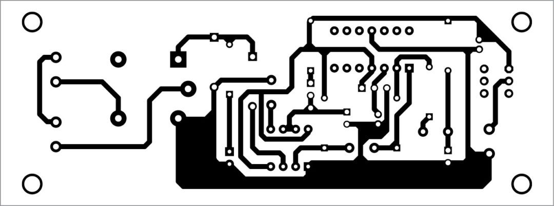
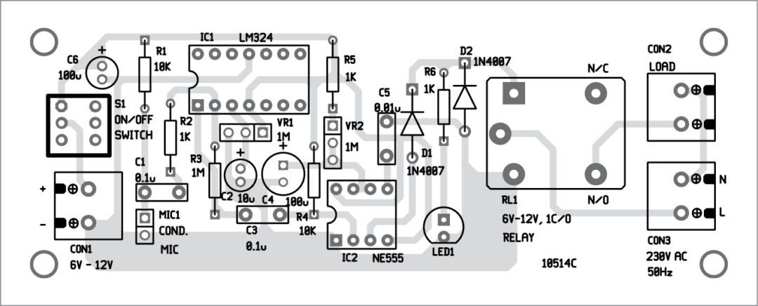
An actual size, single side PCB layout for the sound operated timer is shown in Fig. 2 and its component layout in Fig. 3. After assembling the circuit on the PCB, enclose it in a suitable plastic box.


Download PCB and component layout PDFs: click here
The circuit needs a 6V-12V DC power supply. When MIC1 captures the sound made by an intruder, RL1 gets energised. An electric lamp may be connected via N/O contacts of RL1 along with a bell or an alarm.


Where can I buy these components? I live in US and i am interested in doing diy stuff.
amazon
i am looking for an electronic regulator for common ceiling fan say from the time i go to sleep i want to set wake up time at which time fan stops as alrams is of no use to me., is it avialable or can be made
Use of LM 358 can save space in PCB.If you continue with LM 324, the power supply can be monitored.
can u tell me which software do u use for making pcb layouts ,plz …
I believe the way R4 is connected it will never let pin 2 of IC2 go low voltage which is what triggers the output on pin 3 to go high, I had to remove R4 for mine to work
Sir, where should I connect the pins 5,6,7,8,9,10,12,13&14 of IC1?
LM324 is a Single Supply Quad Operational Amplifier.
Only one amplifier is used here in this project.
So there is no need to connect pins 5,6,7,8,9,10,12,13 and 14 of IC1?
Regards