Lidar plays a key role in cartography, mapping, localisation, ADAS, environment scanning, and more. It is widely used in robots, autonomous vehicles, and for intruder monitoring.
However, many systems are wired, making them cumbersome for prototyping and testing, particularly in autonomous driving, where mounting and connecting a lidar can be difficult.
Here, we present a Wi-Fi-enabled standalone lidar that scans and delivers real-time data wirelessly. Simply connect it to a battery, and it is ready to use—no wiring required.

POC Video in English
This device enables flexible lidar deployment for mapping, monitoring, and similar tasks. We combined the IndusBoard with a lidar unit to scan surroundings, generate data, and create real-time wireless maps displayed on a web page.
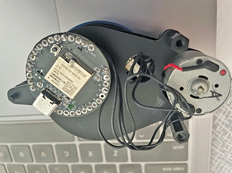
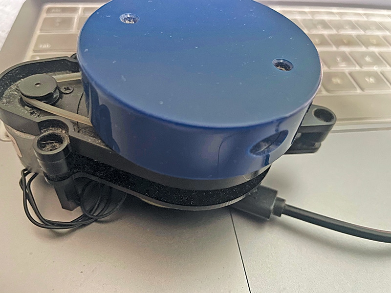
Fig. 1 shows the IndusBoard fixed to the lidar. The components for the project are listed in Table 1. Fig. 2 shows the lidar used during testing.

| Table 1: Bill of Materials | ||
| Components | Description | Quantity |
| IndusBoard | 3cm sized development board | 1 |
| 360-degree lidar | YD X2 lidar | 1 |
| 5V battery | Power source | 1 |
| 3.3V voltage regulator | DC-DC 5V to 3.3V regulator | 1 |
You can select any lidar model; in this project, we used the YD X2 lidar. According to the datasheet, it can scan 360 degrees and measure up to 8 metres, but other lidars can measure up to 1km. Choose based on your requirements.
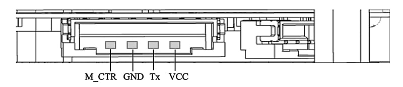
Let’s review the lidar datasheet. The YD X2 lidar provides rotation angle and distance data via serial peripherals at a baud rate of 115200. It includes a connector board for USB connection to a PC (see Fig. 3 and Table 2).
| Table 2: Pin mapping | |||||
| Pin | Type | Description | Defaults | Range | Remarks |
| VCC | Power supply | Positive | 5V | 4.8V-5.2V | / |
| Tx | Output | System serial port output | / | / | Data stream: Lidar to peripherals |
| GND | Power supply | Negative | 0V | 0V | / |
| M_CTR | Input | Motor speed control terminal | 1.8V | 0V-3.3V | Voltage speed regulation or PWM speed regulation |
As shown in Table 3, the lidar senses distances from 0.12 to 8 metres, scanning 360 degrees at 3000Hz. With this data, we can now connect the lidar to the IndusBoard. You can power both components with a 5V battery or an adaptor.
For a portable solution, use the battery; otherwise, the 5V adaptor works well. Fig. 3 shows the lidar connector pins.
| Table 3: Lidar datasheet | |||||
| Item | Min | Typical | Max | Unit | Remarks |
| Ranging frequency | / | 3000 | / | Hz | Ranging 3000 times per second |
| Motor frequency | 5 | 6 | 8 | Hz | Need to connect to PWM signal, recommended to use the speed of 6Hz |
| Ranging distance | 0.12 | / | 8 | m | Indoor environment with 80% reflectivity |
| Field of view | / | 0-360 | / | Deg | / |
| Systematic error | / | 2 | / | cm | Range≤1m |
| Relative error | / | 3.5% | / | / | 1m<Range≤6m |
| Tilt angle | 0.25 | 1 | 1.75 | Deg | / |
| Angle resolution | 0.60 (frequency @5Hz) | 0.72 (frequency @6Hz) | 0.96 (frequency @8Hz) | Deg | Different motor frequency |
Circuit Diagram
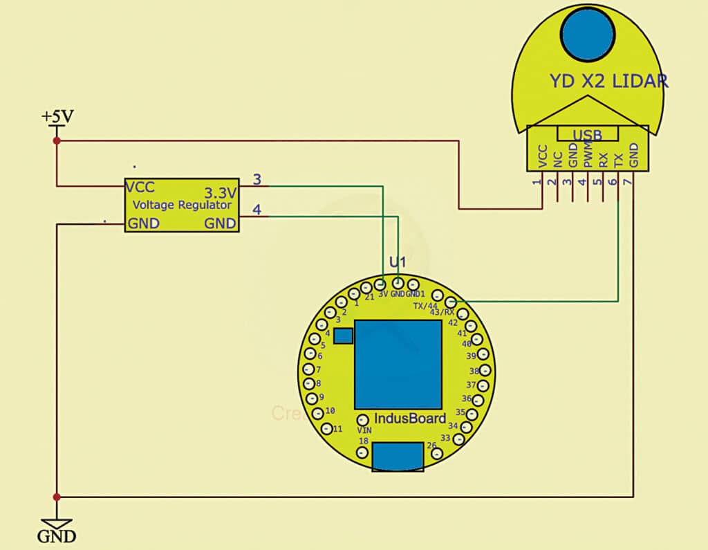
Fig. 4 shows the circuit diagram for the IndusBoard based standalone IoT lidar radar. The device is powered by a 5V battery, with the lidar controlled via PWM signals through the RX pin. Output is sent to the serial port.
Software
Depending on the lidar version, you can use the appropriate Arduino library. Here, a library compatible with the YD X2 lidar to retrieve data was utilised.
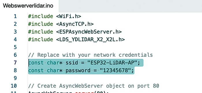
First, configure the Wi-Fi SSID and password in the code. You can connect the lidar to an existing Wi-Fi network or set it as a Wi-Fi access point (AP). In this project, we set the lidar as an AP. Fig. 5 shows the code snippet for configuring the AP.
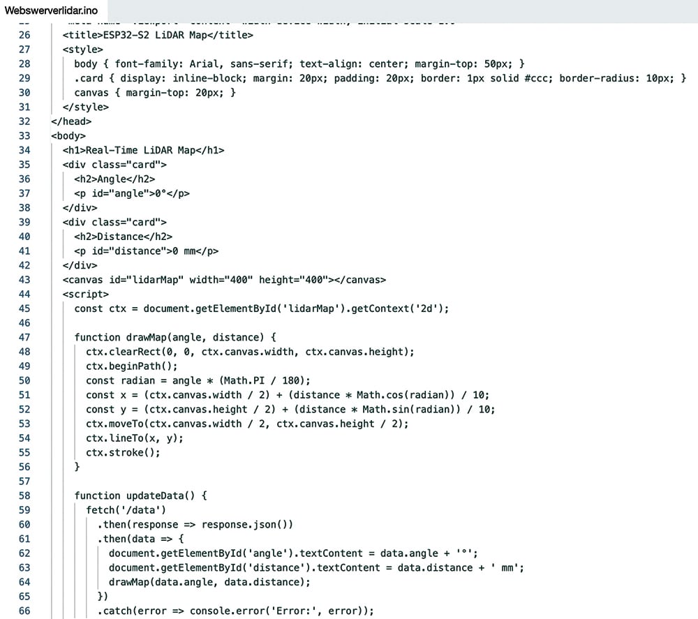
Next, define the serial pins, ports, and PWM motor control pin in the code. Write the web page using HTML, CSS, and JavaScript to display the map and data in real time over Wi-Fi. Fig. 6 shows the web page’s code snippet.
Construction and Testing
After uploading the source code, complete the wiring as per Fig. 4. Connect the lidar motor control pin to any PWM-enabled pin on the IndusBoard. The serial data pin can also be connected to any pin, but in this case, RX pin 43 was used.
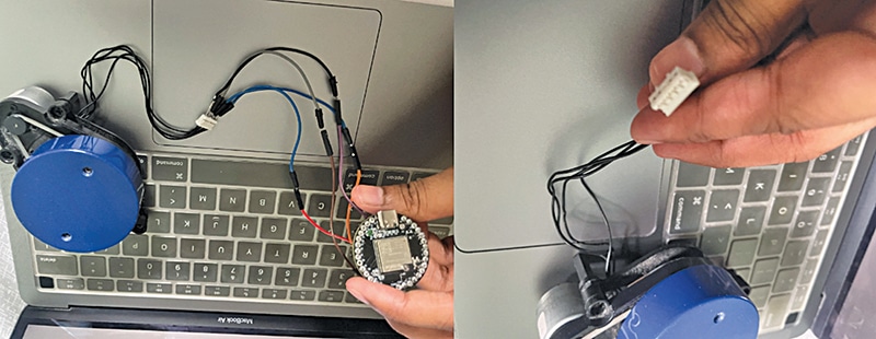
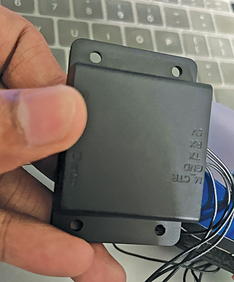
For testing, connect the lidar’s connector either via a header pin or by soldering directly to the board. Mount the IndusBoard and lidar as shown in Fig. 7. The IndusBoard, being small enough, fits behind the lidar. Fig. 8 shows the lidar pin USB connector module, with pin numbers marked.
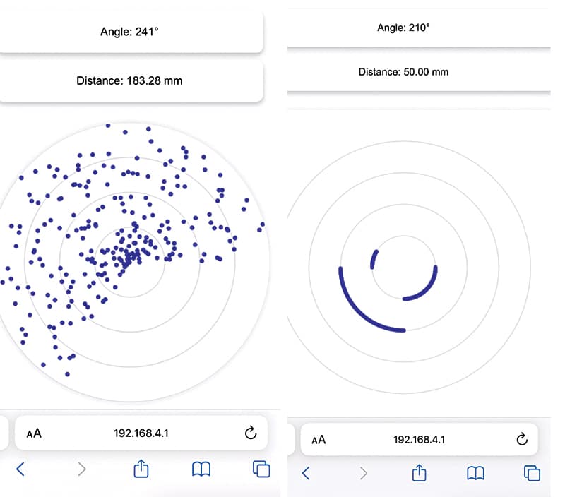
After assembly, power on the lidar and establish a Wi-Fi connection. Open a web browser and navigate to the IndusBoard’s default IP address: 192.168.4.1. The web page will display the real-time map and provide distance and angle data. Fig. 9 shows the lidar scan data plotted on the web page.
Ashwini Kumar Sinha, an IoT and AI enthusiast, is a tech journalist at EFY