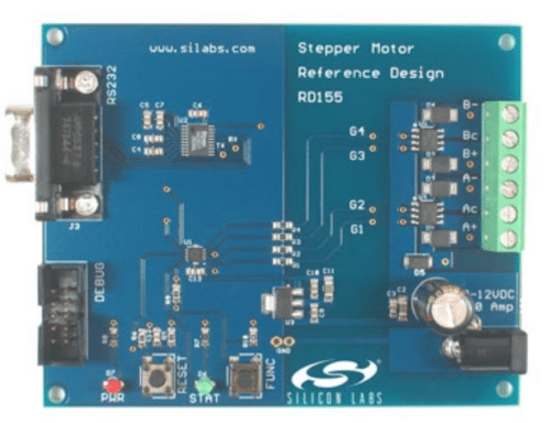
The stepper motor reference design shows how to use a microcontroller for motor applications, offering tools for code development and hardware integration with components.

Stepper motors are used in many different applications. They are commonly found in consumer office equipment like printers, plotters, copiers, and scanners. In automotive systems, they are used for electronic throttle control, dashboard indicators, and climate control.
Stepper motors are also used in industrial equipment, including robotics, electronic component handlers, testers, dispensers, and other manufacturing machinery.
The stepper motor reference design from Silicon Labs shows how to use the C8051F301 microcontroller in high-performance stepper motor applications. It also serves as a platform for developing stepper motor codes. The firmware includes a linear-velocity profiler with adjustable acceleration.
The Stepper motor reference design hardware includes four sections. These are the microcontroller, power electronics, voltage regulator, and serial interface.
The microcontroller is housed in a compact 3 mm by 3 mm 11-lead microlead package (MLP), small enough to be integrated into the most miniature motors. The C8051F30x family includes five devices with different options. The ‘F300 and ‘F301 have a calibrated internal oscillator, accurate to within ±2% at test. This makes the internal oscillator suitable for the UART with baud rates up to 115.2 kbps. The reference design does not use the 8-bit 500 ksps ADC in the ‘F300, so either the ‘F300 or the ‘F301 can be used, as the ‘F301 does not have the ADC. The ADC on the F300 could be helpful in some designs for monitoring the DC motor voltage, stepper motor current, or motor temperature.
The power MOSFET chosen for the stepper motor reference design is the Fairchild FDS8926A. These small, low-on-resistance MOSFETs come in an SO8 package. They were selected for their 30 V rating, 3 V gate, and SO8 package.
A maximum drain-to-source rating of 30 V is needed to drive the 12 V stepper motor, and the selected MOSFET is compatible with a 3 V MCU. The FDS8926A has an on-resistance of 38 mΩ at 2.5 V, making it suitable to handle 2-3 A in this application.
The voltage regulator used is the LM2973-3.3, a 3.3 V low-dropout regulator in an SOT223 package. Its maximum continuous input voltage is 26 V. When selecting a voltage regulator, it’s important to consider the maximum open circuit voltage of the power supply.
The worst-case total VDD current draw for the board is approximately 25 mA, which occurs when both LEDs are on and the serial port runs at 115.2 kbps. Under this condition, the regulator will dissipate around 300 mW of power with an input voltage of 15 V.
Silicon Labs has tested this reference design. It comes with a bill of materials (BOM), schematics, assembly drawing, printed circuit board (PCB) layout, and more. The company’s website has additional data about the reference design. To read more about this reference design, click here.


