


 Portable devices like personal computers, MP3 players, sound recorders, telephones and audible sensors are frequently in need of additional stereo amplifier to produce sufficient sound. These audio amplifiers should work with batteries (4.5V, 6V, 12V, etc) and USB interfaces (+5V).
These should have low quiescent current and produce at least 2×0.5W of output power. This output power is enough for listening in a small room with several people.

Stereo Amplifier Circuit and Working
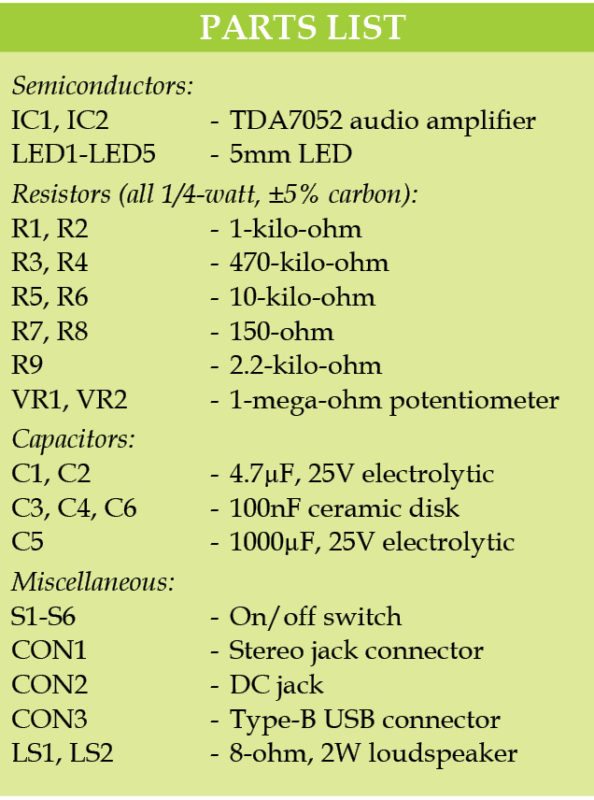
Fig. 1 shows the circuit diagram of a simple stereo amplifier with two TDA7052 ICs (IC1 and IC2) that can be used for portable devices.
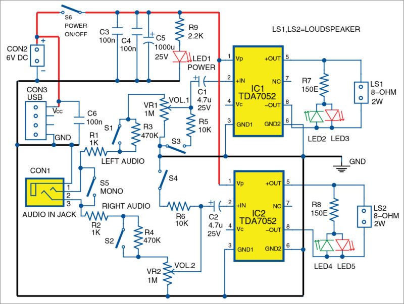
TDA7052 is a 1.2W mono audio power amplifier. It has a wide power supply range (3V to 18V) and can work from USB interfaces. Typical quiescent current of TDA7052 is 4mA, which makes it appropriate for battery operations. Gain of each channel of the circuit is 39dB (around 90). Typical input resistance of TDA7052 is 100-kilo-ohm, and the IC is suitable for a lot of high-impedance signal sources.

The circuit has six switches (S1 through S6). When S1 and S2 are open, input impedance of the circuit is more than 500-kilo-ohm and the amplifier can be used with electrical guitars, high-impedance sensors and signal sources.
When S3 and S4 are closed, input resistance is reduced and, at the same time, output noise is reduced.
S6 works as an on/off switch. The power supply is applied to the circuit through S6.
S5 works as a stereo/mono selector switch. If S5 is closed, the circuit works as a dual-channel mono amplifier. Left and right audio signals coming from connector CON1 are shorted through S5. If S5 is open, the circuit works as a stereo amplifier with two different input signals.
Output power of TDA7052 is typically 1.2W over a load of 8-ohm and with power supply of 6V. The power supply can be increased but the load should have higher resistance, of say, 32-ohm.
The left and right audio channels have separate volume controls, VR1 and VR2, respectively. This avoids the usage of the balance-control potentiometer so that the two channels can also be used separately for the amplification of two mono signals.
Values of VR1 and VR2 should be minimum in order to reduce output noise. Value of C5 should be minimal for the circuit to operate from most USB interfaces.
Construction and Testing
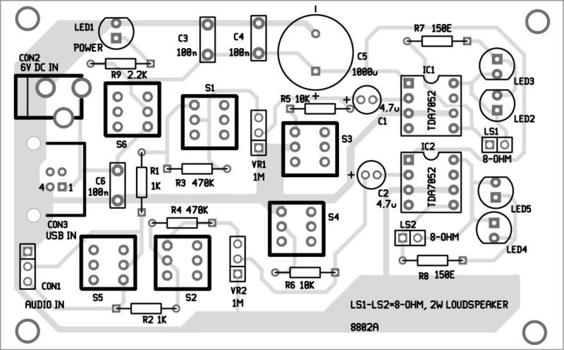
An actual-size PCB layout of the stereo amplifier with two TDA7052 amplifiers for portable devices is shown in Fig. 2 and its component layout in Fig. 3. After assembling the circuit on the PCB, enclose it in a suitable enclosure.
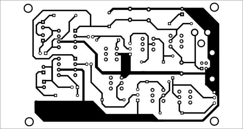
Download PCB and component layout PDFs: click here
The circuit does not need any adjustment and will work immediately after proper assembly. LED2 and LED3 are visual indicators for left-channel audio output, while LED4 and LED5 are for right-channel audio output.
More interesting projects available here.

Can this ckt able to play MP3 songs loaded in USB drives. 2 middle terminals of USB drive are kept open. Can this ckt could be modified to play songs directly from USB drive. Pl suggest.