


Most audio signal sources have only one stereo output, which means they can drive only a single pair of headphones with a resistance of around 32 ohms or a single line of 600 ohms. But sometimes several people are required to connect their headphones to a single audio signal source—such as for entertainment, e-learning and training, or at home. In these situations, use of powerful loudspeakers is not desirable because other people in the room will get disturbed.
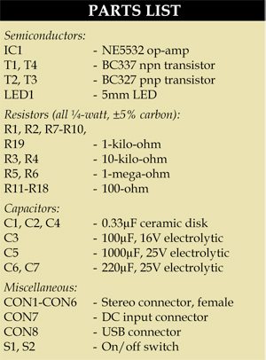
Also, sometimes the signal from one audio output needs to be sent to several power amplifiers located many metres away from each other. In that case, the distribution device should be able to drive long audio lines with resistance between 100 and 600 ohms.

Presented here is a solution to such a requirement that adds a distribution buffer (DB) between the audio output and the headphones. Most headphones have some kind of volume control. Therefore no volume control is added to the distribution buffer to keep the things simple.
Circuit and working
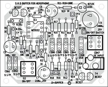
Fig. 1 shows the circuit of the stereo distribution buffer built to solve practical problems that arise when the signal from a single stereo source should be buffered in order to drive up to four headphones or small high-impedance loudspeakers with resistance higher than 32 ohms.

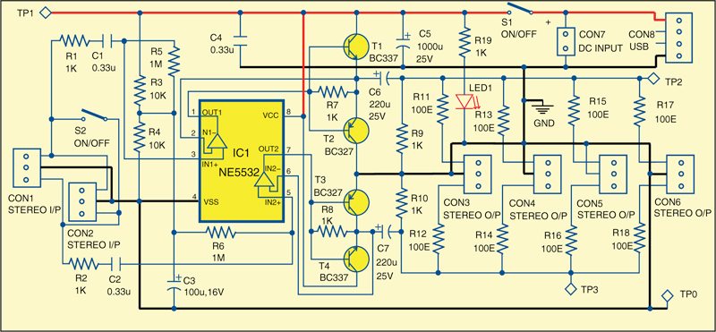
The circuit has two identical channels. Each channel of the buffer has one input and four outputs. The input stereo signal is applied on connector CON1. The same signal is available on connector CON2, so the second distribution buffer can be connected to that connector.
R1 and R2 are resistors for input protection, typically having a value between 100 ohms and 2 kilo-ohms. Their exact value depends on the parameters of the signal source, the cables, the inputs, etc.
C1 and C2 are used to cut the DC input component. If DC voltage from the source is present, the amplifier ill not work properly in most cases. Also, C1 and C2 act as high-pass filterswith the input resistance and should be calculated accordingly as:
F3dB = 1/(6.28×Rinput×C)
The input resistance is 1 mega-ohm and depends mainly on the values of R5 and R6. The gain of each channel is unity. Also, in order to keep the circuit simple, potentiometers for volume control are not included.
When switch S2 is closed, both the inputs come in parallel. The outputs on connectors CON3, CON4, CON5 and CON6 are for headphones or audio interfaces. Any combination of the outputs can be used. The maximum total output current provided by the buffer is around 100 mA.
The buffer itself is built around the dual operational amplifier NE5532 (IC1) and a few discrete components. Other operational amplifiers such as RC4560, OPA2132, TL072, TL082 and even LM358 can be used but it is preferable to use amplifiers for audio which are capable of driving loads of 600 ohms or less and have high input impedance.
The buffer can work with a wide range of power supplies depending on the operational amplifier used. When low-voltage rail-to-rail operational amplifier are used, the buffer will work from a 5V USB power supply. The circuit will also work with 5V/12V DC wall adaptors providing at least 200mA current.
The quiescent current of the buffer is practically equal to the quiescent current of the operational amplifier. There is no nee to put heat-sinks for transistors T1 through T4 but it is preferable to use transistors with a gain of more than 100. T1 through T4 increase the output current of the operational amplifiers. If you remove them, the operational amplifier will not be able to drive long cables and low-impedance head-phones.
Resistors R9 and R10 are used to charge capacitors C6 and C7, respectively, when there is no load. If you remove R9 and R10, you are likely to hear an unpleasant sound of initial charging of the capacitors. The values of R9 and R10 are not critical (1-100 kilo-ohms) but it is suggested to charge C6 and C7 in less than a second.
The output resistance at CON3 through CON6 is around 100 ohms and can be changed by changing the values of the corresponding series resistors R11 through R18. Usually, the values of these resistors are between 100 and 330 ohms. The outputs have series resistors and connecting or disconnecting a load on one output does not affect noticeably the other outputs.
Working of the circuit is simple. Connect the output from the audio source to CON1. The same audio will be available at ports CON3 through CON6 for four different headphones.

Can this circuit be connected to inputs of audio amplifiers ?
I have questions-
1. Can a single 32 ohms headphone be used directly in Line out port of desktop computer without this circuit?
2. Can the normal headphone splitter available locally be used with 5 outputs for using multiple headphones?