- Non-Contact Type Digital Tachometer
- Low-Cost Tachometer
- Simple Tachometer
- DIY Tachometer built with a Microcontroller.
The article was originally published in December 2010 and has recently been updated.
 A tachometer is an instrument that measures the rotational speed of a shaft or disk in a motor or other machine. Here we present the basic version of the tachometer that shows the revolutions per second (RPS) on a digital display.

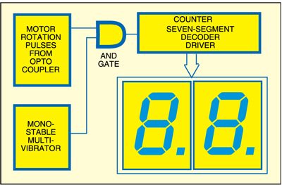
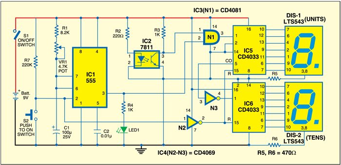
Fig. 1 shows the block diagram of the tachometer. Fig. 2 shows the circuit of the tachometer, which is built around timer IC 555 (IC1), IC 7811 (IC2), IC CD4081 (IC3), IC CD4069 (IC4), two CD4033 ICs (IC5 and IC6) and two common-cathode displays (each LTS543) along with some discrete components. IC1 is wired in monostable mode and produces 1-second pulse when triggered by switch S2. Variable resistor VR1 is used for setting the time period of IC1. IC2 generates pulses when the shaft is moving.
IC5 (CD4033) is a decade counter with seven-segment decoded output, which is connected to DIS1 for displaying unit’s place. Pins 2 and 14 of IC5 are grounded. Pin 5 (CO) of IC5 provides a pulse when the count overflows (count reaches from 0 to 9). This pulse is used as the clock input to IC6 via NOT gate N3. That is, after ten pulses from IC5, there will be an increment of one pulse in IC6. Thus when the unit’s counting completes in DIS1, further counting is shown on DIS2. A maximum of 99 digits can be counted and shown on DIS1 and DIS2.
Tachometer circuit

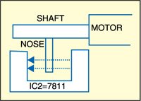
Working of the circuit is simple. Place IC2 such that when the motor shaft rotates, it cuts the IR signal to produce pulses at its output pin 3. That is, as the motor rotates, the shaft cuts the internal light beam within the slot of the optocoupler (IC2). As a result, pulses are generated. This train of pulses is applied to input pin 1 of AND gate N1. Pin 2 of AND gate N1 is connected to output pin 3 of IC1.
To measure the RPS of the shaft, press switch S2 momentarily to enable gate N1 for time duration of one second via the monostable multivibrator (IC1). The pulses are applied as clocks to IC5. The counter increments and generates the code to drive the seven-segment displays. The displays show the number of counts in one second. Accordingly, you can simply calculate revolutions per minute (RPM).

Construction & testing
Assemble the circuit on a general-purpose PCB and enclose in a cabinet with enough space for the battery, switches and motor. Connect the 9V battery and the module is now ready to display the RPS of the motor. As shown in Fig. 3, fix a nose on the motor shaft so that it can cut the internal IR beam of the optocoupler.
Related Techometer Projects
- Non-Contact Type Digital Tachometer
- Low-Cost Tachometer
- Simple Tachometer
- DIY Tachometer built with a Microcontroller.
The article was originally published in December 2010 and has recently been updated.


Please give me correct layout of this circuit …i m really thankfull to you …
PCB layout is not available for this circuit.
Hi, do you have a replacement for the 7811 optocoupler and CD4033 decade counter? It is hard to find them in electronics parts store.
what is N1gate in diagram
N1 is AND logic gate
the display will hold the rps reading and update every second. max is 99 rps.
Hello
Which simulation software did you use for simulation?
No simulation software was used during testing. However, you may try with any suitable software
Sir, can I use individual current limiting resistance for each segment of the seven segment display instead of using single resistor in common cathode pins (R5&R6)?
Yes, you can also use individual current limiting resistance for
each segment of the seven segment.