


 This project is used to control the movement of the spray head and nozzle in a thin metal or insulation film deposition system. Here, AT89C51 or P89V51RD2 microcontroller (MCU) is used to control the spray head and nozzle in x and y directions. It is an inexpensive, simple and efficient solution for a flat surface. The setup of the thin-film deposition controller using MCU is shown in Fig. 1.
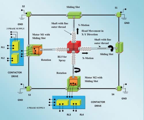
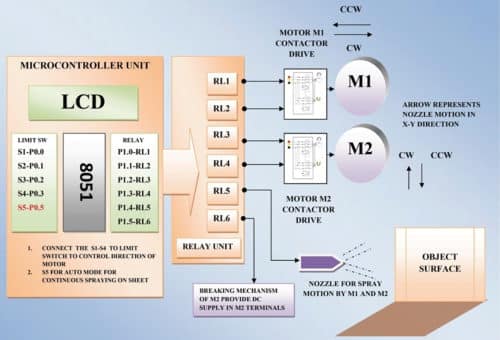
In this technique, the spray head—which contains fine sprays of molten metal for spray coating over a flat surface—moves in x and y directions on the sheet of a given job. It is controlled and guided by an MCU using two motors and four limit switches with mechanical support structure, as shown in Fig. 1. Block diagram of the thin-film deposition controller using MCU is shown in Fig. 2.
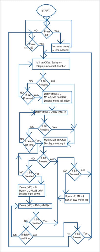
Flow chart of the circuit is shown in Fig. 3.

Circuit and working
The circuit diagram of the thin-film deposition technique using MCU is shown in Fig. 4.
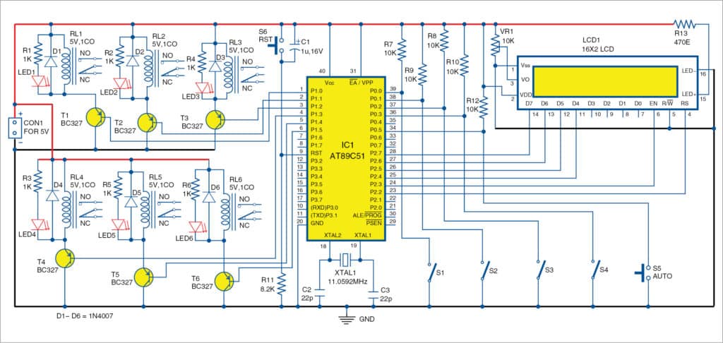
It is built around AT89C51 MCU (IC1), 16×2 LCD (LCD1), six 5V, 1CO relays (RL1 through RL6), six 1N4007 rectifier diodes (D1-D6), six LEDs (LED1 through LED6), six pnp transistors (T1 through T6), two low-rpm 3-phase motors along with 3-phase contactors, DC-operated nozzle, limit switches (S1 through S4) and a few other components.
The spray head is moved in x and y directions using two 3-phase motors (M1 and M2), controlled by the MCU in clockwise (CW) and counter-clockwise (CCW) directions, as shown in Fig. 1. The motors have shafts with fine threads.
Here, AT89C51 is the main controller of the circuit. It controls 5V relay units from its port pins P1.0 through P1.5. Each relay is connected to relay driver transistor BC327. Each transistor is triggered by the corresponding input limit switch connected at port pins P0.0 through P0.3, and P0.5 of IC1. It has a 16×2 LCD user-interface display unit connected at port 2, for the display of various parameters during run time, as shown in Fig. 4. LCD1 is configured in 4-bit mode.
When power is applied to the circuit, it checks the condition of S1. If S1 is pressed or grounded, MCU gives a command to drive RL1 for M1 in CCW direction, to start or move from its home position in CCW direction until S2 is pressed.
When S2 is pressed, RL3 is energised, and spray head moves down as per the settings. After a few delays, RL2 is energised and the head moves in CW direction. This cycle repeats until S3 or S4 is pressed. You can control the head movement anytime during run time using S3 or S4.
Left and right movements
M1, S1 and S3 are responsible for left and right movements of the spray head. RL1 is energised for CCW direction and RL2 for CW direction. Refer Fig. 5 for different movements of the spray head.

Down and up movements
M2, S2 and S4 are responsible for down and up movements. RL3 and RL4 are energised for down and up directions, respectively.
Relay connections
The 3-phase induction motor connections in CW and CCW directions are shown in Fig. 6.
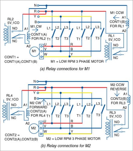
RL1 and RL2 are used to drive M1 in CW and CCW directions, respectively, via contactor1. It has two separate individual contactors, CONT1 (A) and CONT1 (B).
RL3 and RL4 are used to drive M2 via contactor2. It also has two separate individual contactors, CONT2(A) and CONT2(B).
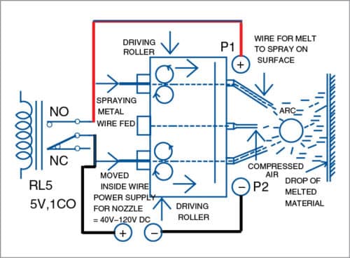
RL5 is used to drive the nozzle. Its circuit is shown in Fig. 7.
An optional relay (RL6), as shown in the circuit, is not used here. S5 is used in auto mode to scan and spray the whole surface of the sheet a number of times, until the MCU is forced to reset, or the circuit is switched off.
Software
Software is written in C program. Kiel µVision is used to generate hex code. Before using AT89C51 MCU in the assembled PCB, burn the hex code into the MCU using a suitable programmer.
Download source folder
Construction and testing
An actual-size PCB layout of the thin-film deposition technique using MCU is shown in Fig. 8 and its components layout in Fig. 9.
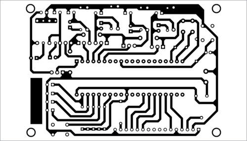
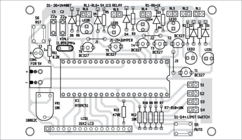
Download PCB and Component Layout PDFs: Click here
After assembling the circuit on the PCB, connect the relays to the respective motor and contactor according to the circuit given in Fig. 6.
Also, connect the nozzle to RL5 according to the circuit shown in Fig. 7. Use external wires to connect 3-phase motors, contactors, nozzle and related circuitry. Mount limit switches at appropriate locations so that S1 is on the right and S2 is on the left, as shown in the setup in Fig. 1.
Testing procedure
-
- Switch on the power supply to the circuit. The head should be at the top-right side near S1.
- Configure the vertical down movement (y direction) of M2 after completion of movement in both left or right directions (x direction) by pressing S4 to get appropriate delay of, say, one second, two seconds, three seconds and so on, followed by pressing S3.
- Press S5 to start in auto mode. M1 starts rotating in CCW (RL1 is on and other relays are off) and the head moves towards S2.
- When head touches S2, M1 stops for some time as per delay settings in step 2. And, M2 gets activated and the head moves downwards.
- M1 gets activated in CW direction automatically. And, the head starts moving from left to right.
- The cycle (steps 4 through 6) repeats until S3 or S4 is pressed.
- Conditions for S3 and S4 are as follows. During run time, when S3 is pressed, the head moves in CW direction automatically. If S4 is pressed, the head immediately moves from the bottom towards home position.
EFY note
The project was tested with 5V, low current rating relays. It is recommended to use proper relays with sufficient current and voltage ratings.
Jitendra Jangid is an electronics engineer. His hobbies include circuit designing and PCB making, and programming embedded systems like Arduino and 8051.
Mahesh Jangid is an electronics hobbyist.
Build your network to transmit high power current from circuits by using high grade electronic components like semiconductor, diodes, transistor, resistor and all providing by Naina semiconductor components.