


 Many of our costly appliances require three-phase AC supply for operation. Failure of any of the phases makes the appliance prone to erratic functioning and may even lead to failure. Hence it is of paramount importance to monitor the availability of the three-phase supply and switch off the appliance in the event of failure of one or two phases. The power to the appliance should resume with the availability of all phases of the supply with certain time delay in order to avoid surges and momentary fluctuations.
Three phase appliance protector
The complete circuit of a three phase appliance protector is described here. It requires three-phase supply, three 12V relays and a timer IC NE555 along with 230V coil contactor having four poles.
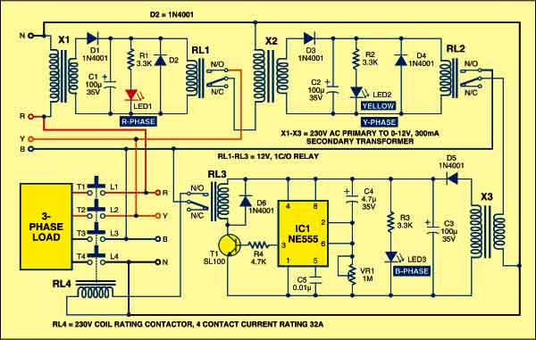
Relays RL1 and RL2 act as a sensing devices for phases Y and B, respectively. These relays are connected such that each acts as an enabling device for the subsequent relay. Therefore the combination of the relays forms a logical AND gate connected serially.

Circuit operation
The availability of phase R energises relay RL1 and its normally-opened (N/O) contacts close to connect phase Y to the input of transformer X2. The availability of phase Y energises relay RL2 and its N/O contacts close to connect phase B to the input of transformer X3, thus applying a triggering input to timer IC NE555 (IC1).
Therefore the delay timer built around NE555 triggers only when all the phases (R, Y and B) are available. It provides a delay of approximately four seconds, which energises relay RL3 and its N/O contact closes to connect the line to the energising coil of four-pole contactor relay RL4. Contactor RL4 closes to ensure the availability of the three-phase supply to the appliance.

The rating of contactor RL4 can be selected according to the full-load current rating of the appliances. Here the contact current rating of the four-pole contactor is up to 32A. The availability of phases R, Y and B is monitored by appropriate LEDs connected across the secondary windings of transformers X1, X2 and X3, respectively. Hence this circuit does not require a separate indicator lamp for monitoring the availability of the three phases. When phase R is available, LED1 glows. When phase Y is available, LED2 glows. When phase B is available, LED3 glows.
The main advantage of this protector circuit is that it protects three-phase appliances from failure of any of the phases by disconnecting the power supply through the contactor and automatically restores the three-phase supply to the appliance (with reasonable time delay) when all the phases are available.
Construction & testing
Assemble the circuit on a general purpose PCB and enclose in a cabinet with the relays and contactor mounted on the backside of cabinet. Connect the appliance through external wires.
Caution
To avoid the risk of electric shock, ensure that AC mains is disconnected during assembly of the circuit and double check everything before connecting your circuit to the mains.
The article was first published in August 2008 and has recently been updated.
