 Wooden-case, battery-operated wall clocks with pendulums are available in the market. Some even have chimes. What is missing is the tick-tock sound of old mechanical pendulum clocks.
Tick-tock sound generator circuit


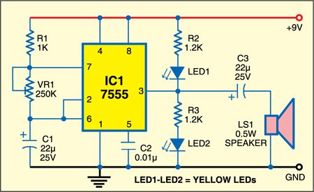
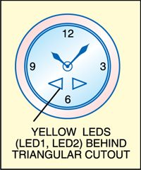
Shown above is the circuit of a tick-tock sound generator. It is built around timer IC 7555 (IC1) wired as an astable multivibrator. Resistor R1, preset VR1 and capacitor C1 generate frequencies that can be varied with the help of preset VR1. At output pin 3 of IC1, a small speaker is connected via capacitor C3 that produces the tick-tock sound. At pin 3 of IC1, two yellow LEDs are also connected on the clock face to flash in time with sound (see Fig. 2). Adjust preset VR1 such that ticking sound closely resembles the tick-tock of old pendulum clocks. Yellow LEDs (LED1 and LED2) match well with the wooden clock.
LED pendulum circuit
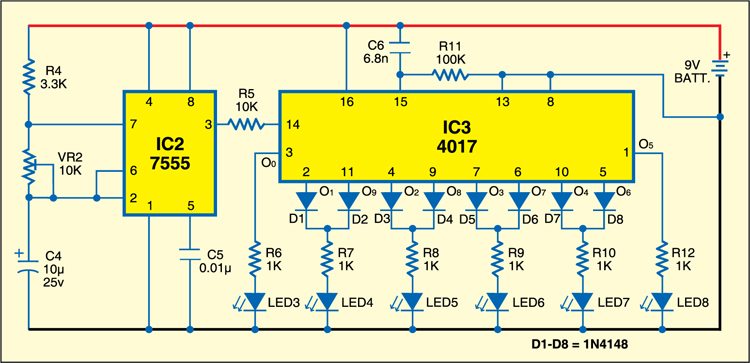
Shown below is the circuit for the LED pendulum. It uses another timer 7555 wired in astable mode and its clock pulse at pin 3 is fed to clock pin 14 of decade counter 4017 (IC3). The outputs of IC3 are connected with the help of switching diode 1N4148 such that the six LEDs (LED3 through LED8) flash in sequence in one direction first and then in reverse sequence. The speed of flashing of LEDs can be adjusted with the help of 10-kilo-ohm preset VR2. Capacitor C6 (6.8nF) and resistor R11 (100-kilo-ohm) are used to reset the decade counter.

Construction & testing
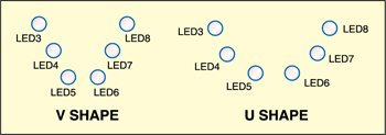
Assemble the circuit on a general-purpose PCB and enclose in a suitable cabinet. Mount the LEDs either in ‘V’ shape or ‘U’ shape on the front panel of the cabinet (as shown in Fig. 4).

The article was first published in June 2009 and has recently been updated.


I have with interest read the article Clock Tick-Tock Sound Generator & LED Pendulum. I have a 200 year old clock win which I had to replace the old clock work with an battery driven one. I miss the tic-tock sound. I am not in the position to assemble such a device. Where will I find someone who can make one for me?