 This is a new type of touch alarm that uses an RF oscillator at its input. One special feature of this touch alarm is that it can use a big-size touch plate. Also, no shielded wire is required between the touch plate and the circuit.
Circuit and working
Fig. 1 shows the circuit of the touch alarm, which is built around CD4060 (IC1), timer 555 (IC2) and a few discrete components. IC1 contains an easy-to-use astable or oscillator stage, followed by a 14-stage binary counter/divider.
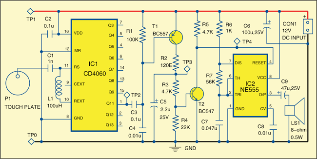
Pulses from the oscillator stage are fed to the 14-bit binary counter stage. Not all the outputs of the binary counter are available externally. The frequency at pin 7 (Q3) of IC1 is actually divided by 24=16 compared to the initial astable frequency. Similarly, Q4 will have half the frequency of Q3. Reset pin (pin 12) is connected to ground to enable the pulses.
IC1 generates an astable frequency of around 4 MHz using low-cost inductor L1. The frequency available at pin 1 (Q11) of IC1 is around 1 kHz, which is actually astable frequency divided by 212. This frequency keeps transistor T2 conducting. Pin 4 of IC2 is held low as long as transistor T2 conducts.
When you touch the touch plate, the oscillator stops working because of loading. No output signals are available at pin 1 of IC1, due to which transistor T2 stops conducting. When transistor T2 is non-conducting, pin 4 of IC2 is high, activating the alarm. The frequency of sound can be changed by changing the value of timing components R6, R7 and C7.
Construction and testing
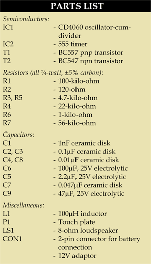
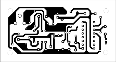
An actual-size, single-side PCB for the touch alarm is shown in Fig. 2 and its component layout in Fig. 3. After assembling the circuit on a PCB, enclose it in a suitable case.
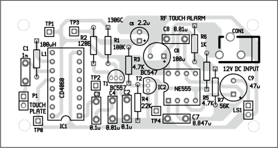
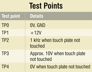
To test the circuit, check correct power supply at TP1 with respect to TP0. Do not touch the touch plate and verify 1kHz (approx.) frequency at TP2. This frequency will die if you touch the touch plate. At TP3 and TP4, verify voltage levels as indicated in the table.


