


 Touch switches are used in many lamps and wall switches that have a metal exterior as well as on public computer terminals. A touchscreen includes an array of touch switches on a display. Basically, a touch switch is the simplest kind of tactile sensor. Described here is a touch switch circuit that operates only when you touch two conductor terminals (say, A and B) simultaneously with your fingertip.
Circuit and working of Touch Switch
A simple touch switch circuit diagram is shown in figure 1. It is built around four BC547 transistors (T1 through T4), a 5V single changeover relay (RL1), two 1N4007 diodes (D1 and D2) and two touch plates (TP1 and TP2). The circuit works off 5V DC.
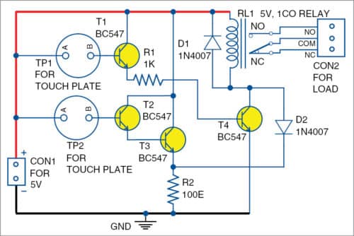
Working of the circuit is straightforward. When TP1 is touched, the base voltages of transistors T1 and T4 go high. As a result, relay RL1 energises to activate the load (light or fan) through relay contacts.

When TP2 is touched, the base voltage of transistor T2 goes high and transistor T3 conducts. The voltage developed across resistor R2 de-energises relay RL1 to de-activate the load.
Touch plates TP1 and TP2 can be made from copper wires or copper plates.

Construction and testing
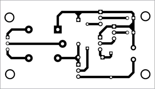
An actual-size PCB layout for the touch switch is shown in figure 2 and its components layout in figure 3. After assembling the circuit, enclose it in a suitable box. Affix the touch plates on the front panel of the box such that you can touch them easily.

This circuit is quite critical. It may works just selecting the coil of the relay at the right point so that with 100 ohm (R2) let pass not enough current for the relay to attract the actuator, or vice versa selecting R2 with the same purpose. The circuit works exploiting the fact that relais need a peak current to move the actuator, and this current is provided by T4 when it enter in conduction because receiving current in its base from T1 when touching TP1.
In this circuit the relay is always energized but the brief instant when one touch TP2.
You can easily operate the RELAY by simple touxching the TP1 & TP2. For better performance you have to supply constant 5VDC Voltage and >1ADC Current.
If anyone sill had some query then they can ask me anything about this TOUCH SWITCH.
Linkedin ID.- click here