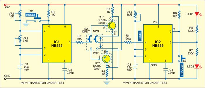
 With this transistor tester, you can test both npn and pnp transistors using this circuit. The circuit indicates whether the transistor is good, open or shorted through two light-emitting diodes (LEDs).
Transistor tester circuit

The circuit comprises two NE555 timer ICs: one (IC1) is wired in the astable mode and the other (IC2) in the monostable mode. The time period of the astable multivibrator is around 0.5 second. Its output goes to the base of the npn/pnp transistor under test via DPDT switch S2.
Switch S2 selects the npn/pnp transistor you are going to test, which means that at a time only an npn or a pnp transistor can be tested. The collector of npn or pnp transistor goes to reset pin 4 of the monostable (IC2). Switch S3 is used to trigger the monostable. The time period of the monostable multivibrator is around two seconds.

Circuit operation
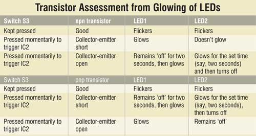
To test a transistor, insert it at the appropriate place shown within dotted lines and slide switch S2 towards the transistor type (npn or pnp) being tested. From glowing of LED1 and LED2 on triggering of the monostable via switch S3, you can infer whether the transistor is good, short or open-circuited, as shown in the table.
The article was first published in November 2005 and has recently been updated.


