 Here is a simple triple mode tone generator circuit that generates three different tones. You can use it as a call bell, burglar alarm or any other security alarm.
Triple Mode Tone Generator Circuit

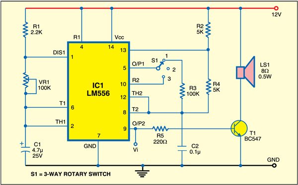
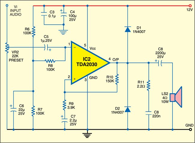
Fig. 1 shows the circuit of the triple mode tone generator, while Fig. 2 shows its extension for an automobile horn. The circuit operates off a 12V battery. At the heart of the circuit is an LM556 dual timer IC having two separate LM555 timers built into it. The first timer is configured as an oscillator with a wide frequency range. The second timer is triggered by the output of the first timer. The circuit produces three sounds depending on the position of the rotary switch (S1). S1 is a single-pole, three-way switch.
Circuit operation
When switch S1 is at position 1, the output of the second timer at pin 9 produces a two-tone sound. When switch S1 is shifted to position 2, the output of the second timer at pin 9 produces a continuous tone. When switch S1 is shifted to position 3, the output of the second timer at pin 9 produces a tone burst. Since LM556 can sink only 200mA current, transistor T1 is used to amplify the output of the second timer and according to the tone, the speaker sounds.

To get louder sound or make an automobile horn, connect the output of the second timer at pin 9, after disconnecting from resistor R5, to audio signal Vi (Fig. 2). The TDA 2030 amplifier provides a high output current with very low harmonic and cross-over distortion. A conventional thermal shut-down system is also included in it.
Assemble the two circuits on separate general purpose PCBs. The PCBs can be housed in a suitable enclosure.
The article was first published in July 2010 & has recently been updated.


Please post PCB layout for this circuit