 Nowadays, most portable electronic gadgets are powered by USB adaptors. These adaptors have 5V, 1A to 5V, 2.1A output, which is enough to power low-power circuits of different voltages while testing a prototype. This is done either by using charge pumps or suitable converters. Presented here is a USB based triple power supply circuit to derive three voltages (3.3V, 5V and 12V) from a USB adaptor.
Circuit and working
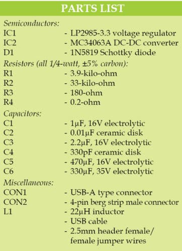
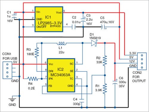
As shown in Fig. 1, the circuit is built around low-dropout voltage regulator LP2985-3.3 (IC1), monolithic DC-DC converter MC34063A (IC2) a Schottky diode 1N5819 (D1), 22µH inductor (L1) and a few other components.
Fig. 1: Circuit diagram of the USB based triple power supply
Here, MC34063A is configured in boost converter mode. IC2, inductor L1 and diode D1 form the boost converter to convert 5V into 12V. Any readily available inductor can be used in place of L1. Resistors R1 and R2, along with 1.25V reference voltage of IC2, are used to set the output voltage using the relationship given below:
Vout=1.25[1+(R2/R1)]
Resistor R4 turns off the switching cycle when the peak current of the internal switch goes beyond the limit.
Capacitor C6 smoothens the ripple produced during every switching cycle. IC1, a fixed-output and low-dropout regulator, converts 5V into 3.3V. Capacitor C2 bypasses ripples to ground. Capacitors C3 and C5 act as buffers. Thus, all three voltages (3.3V, 5V and 12V) are available at CON2. Jumper wires can be used at CON2 to power external circuits.
Construction and testing
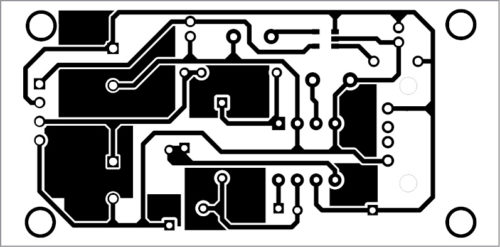
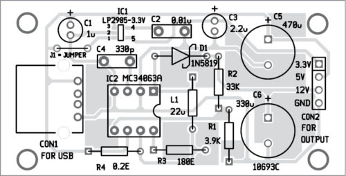
A PCB layout of the USB based triple power supply is shown in Fig. 2 and its components layout in Fig. 3. After assembling the circuit on the PCB, enclose it in a suitable plastic box with CON1 fixed at the rear side and CON2 at the front side of the box.

Fig. 2: PCB layout of the triple power supply

Fig. 3: Components layout for the PCB
Download PCB and component layout PDFs: click here
IC1 should be placed on solder side of the board. Use USB-A type connector as CON1.
After assembling the PCB, connect the USB to a laptop. Now your power supply circuit is ready to use.

Note. 1. The maximum current for 3.3V and 12V depends on the current provided by USB port.
2. Since 5V is directly available from the USB, keep the overall current of this circuit below 20-25 per cent of the maximum current of the USB from which the circuit is powered.


