


Here is a simple circuit of TV to FM converter. With this simple one-transistor BF494 circuit. you will be able to receive FM and VHF stations on your old Black And White TV sets.
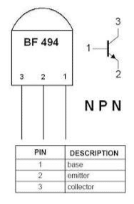
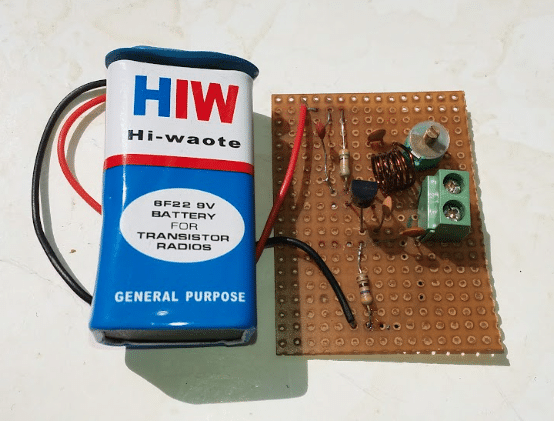
The circuit uses only one NPN transistor T1, BF494 and a few other components. A + 6V power supply for this circuit could be taken from a TV set or use a 9V battery separately.
Parts List
Semiconductor

- T1: BF 494
Resistors
- R1: 470kΩ
- R2: 470Ω
Capacitors

- C1: 0.01µF
- C2: 10pF
- C3: 33pF
- C4: 0.001µF
- C5: 0.01µF
- VC1: 2-22pF trimmer capacitor
Inductor
- Coil L*: 5 turns of 23 SWG wire on a 5mm air core
Additional Components
- Wires
- 2-pin connectors
- 9V battery
- Switch (for ON/OFF functionality)
TV to FM Converter Circuit
A BF494 transistor, along with resistors R1 and R2, is used to bias the transistor. Capacitor C1 is connected to the base of T1 and the +9V supply, while capacitor C2 is connected between the base and emitter.
This configuration forms an oscillator circuit that generates frequencies in the range of 93.5 MHz to 113.5 MHz.
Transistor T1 also functions as a mixer, combining the oscillator frequency with input signals in the range of 88.00 MHz to 108.00 MHz. The resulting output is an SIF signal at 5.5 MHz, which is then fed into the 5.5 MHz IF input of your TV set.
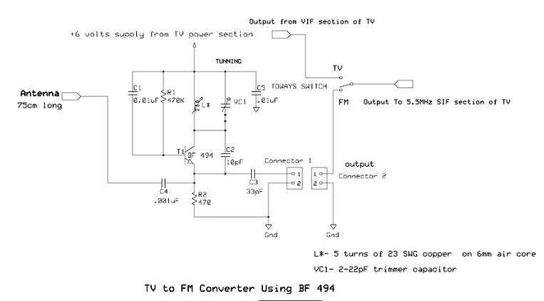
An inductor (L*) is connected in parallel with a trimmer capacitor (VC1, 2-22pF) and to a +6V power supply. This setup is linked to the collector terminal of a BF494 transistor.
A 75cm long wire antenna is connected to the emitter of the BF494 transistor through a 0.001µF capacitor (C4). This antenna helps amplify weak signals.
Capacitor C1 is connected between the base of the BF494 transistor and the +Vcc supply. Capacitor C2 (10pF) is placed between the collector and emitter of the BF494, providing feedback to sustain circuit oscillation. Capacitor C5, connected between the +9V power supply and ground, acts as a DC power filter.
The 5.5MHz output signal is taken from the emitter of the BF494 via a 33pF capacitor (C3) and connected to the SIF input of a TV through a switch.
Construction and Calibration
- *Inductor (L)**: Wind 5 turns of 23 SWG wire on a 6mm air core to form the inductor.
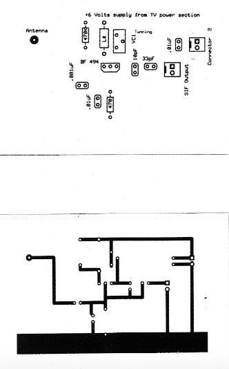
- Circuit Board: Use a 5cm x 7cm Vero board to assemble the FM receiver circuit.
- Trimmer Capacitor (VC1): Allows for tuning to different FM stations.
Connect a 9V battery to the circuit and attach the output terminal to the SIF input of a TV. Turn on the TV, and you will hear a hissing sound. Slowly adjust the VC1 trimmer or tweak the coil (L*) by pulling its turns closer or further apart until a nearby FM station is tuned in.
If signals are weak, you can use a 75cm long wire as an antenna to improve reception.
Also Check:


what is diffrence between c4 and c5?
Value of both capacitors are different.
C4:.001uF and C5:.01uF. Also C4 is used to connect an
Antenna, while C5 is used for to reduce the noise.