 Motor driver modules for motors allow you to control the working speed and direction of two motors simultaneously. Here we present an alternative ULN2803 based motor driver circuit to drive two motors. The main advantage of this project is its low-cost design.
Circuit and working
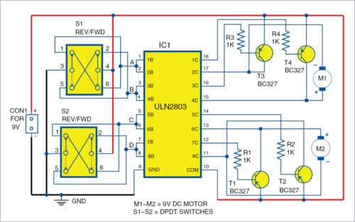
The circuit of bi-directional DC motor control is shown in Fig. 1. It consists of ULN2803 high-current Darlington transistors array pack (IC1), four pnp BC327 transistors (T1 through T4), four resistors (R1 through R4), two switches (S1 and S2) to control motors in forward and reverse directions, and a 9V DC power supply.

Transistors T1 and T2 control motor M2, while transistors T3 and T4 control motor M1. Pin 9 of IC1 is ground and pin 10 is connected to 9V. Working of the two motors (M1 and M2) is explained in Tables I and II, respectively.
Case 1 (M1)
The internal transistor packs of ULN2803 act as inverters. When point A=0 and B=1, output pins 17 and 18 will be high (9V), and pins 15 and 16 will be active-low (0V) as shown in the circuit. The base of pnp transistor T4 is high through resistor R4, so T4 is in cut-off state. Similarly, the base of transistor T3 is low through resistor R3. So T3 conducts to make 9V available at one of the terminals of motor M1. The second terminal of M1 is at zero volt (GND). So motor M1 rotates in one direction, say, forward direction.
Case 2 (M1)
When point A=1 and B=0, output pins 17 and 18 of IC1 will be low (0V), and pins 15 and 16 will be active-high (9 volts). The base of transistor T4 becomes low through resistor R4, so T4 conducts. Similarly, the base of transistor T3 is high through resistor R3, and so T3 is in cut-off state. There is no voltage (0V) available at the first terminal of M1, while the second terminal gets 9 volts. In this case, M1 rotates in opposite direction, say, reverse direction.
Case 3 (M2)
When point C=0 and D=1, output pins 13 and 14 of IC1 will be high (9V), and pins 11 and 12 will be active-low. Transistor T2 is in cut-off state and transistor T1 conducts. Motor M2 rotates in one direction, say, forward direction.
Case 4 (M2)
Similarly, when point C=1 and D=0, output pins 13 and 14 of IC1 will be low, and pins 11 and 12 will be active-high (9 volts). Transistor T2 conducts and T1 is in cut-off state. Motor M2 rotates in the opposite direction.
If all the inputs (A, B, C and D) are at logic 0 (GND), both the motors will be in stop condition because there will be no voltage differences at the motors’ terminals.
Note. If all the inputs are at logic 1 (9 volts), transistors will burn out. So it is not recommended to apply both the input terminals with the same high voltages in this circuit configuration.
Construction and testing of ULN2803 Based Motor Driver Circuit
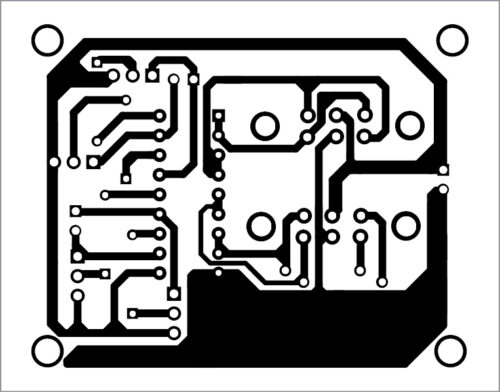
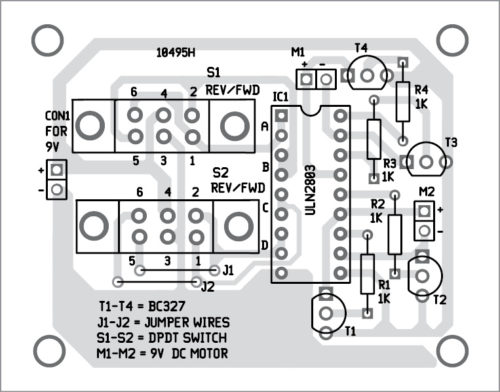
An actual-size PCB layout of the bi-directional DC motor control circuit is shown in Fig. 2 and its components layout in Fig. 3. Assemble components on the PCB. Connect motors at M1 and M2 markings on the PCB. Connect a 9V PP3 battery for power supply to the circuit. You can use double-pole double-throw or slide switches for S1 and S2.


Download PCB and component layout PDFs: click here


Full of knowledge & easy to understand…
Thank you for your valuable feedback.