


 This ultrasonic proximity detector comprising independent, battery-powered transmitter and receiver sections makes use of a pair of matched ultrasonic piezoceramic transducers operating at around 40 kHz each. This circuit can be used in exhibitions to switch on prerecorded audio/video messages automatically when a visitor evincing interest in a product comes near an exhibited product.
Ultrasonic Proximity Detector
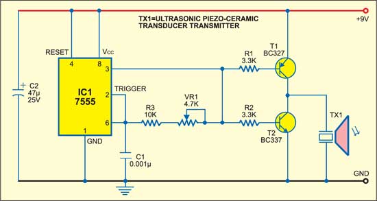
Fig. 1 shows the transmitter circuit. It comprises CMOS timer IC 7555 (IC1) configured as an astable multivibrator, which may be tuned to the frequency of the ultrasonic piezoceramic transmitter’s resonant frequency of around 40 kHz using preset VR1. A complementary pair of transistors T1 and T2 is used for driving and buffering the transducer while it draws spikes of current from IC1 circuit to sustain oscillations and thereby avoids any damage.
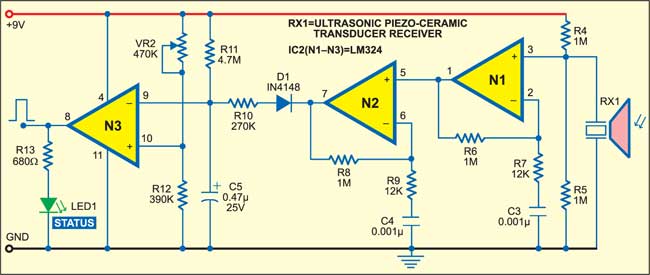
The receiver front-end (refer Fig. 2) is designed to provide a very high gain for the reflected faint ultrasonic frequency signals detected by the ultrasonic transducer. The amplifiers built around N1 and N2, respectively, provide AC voltage gain of around 80 each. These two stages should have a high open-circuit gain, wide bandwidth and very low bias current apart from being capable of single-supply operation. Quad op-amp LM324 is used here due to its low cost. For higher efficiency, you may use single op-amps such as CA3130 or CA3140.

Circuit operation
When a visitor pauses before a resistor R10 is used to meet this requirement. The filter also helps to bypass brief bursts of ambient noise in the ultrasonic range. The third stage comprising N3 works as a comparator to provide a triggering pulse when a visitor stops by. This pulse can be used to trigger a timer or a monostable, whose output may then be used to switch on the audio/video message concerning the product for a predetermined period.

When somebody comes in front of the ultrasonic piezoceramic transducer pair, the status LED (LED1) glows because of the signal reflected from the body of the visitor.
Construction & testing
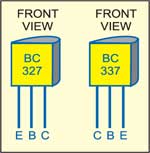
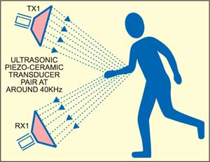
The circuit can be assembled on any general-purpose PCB. The transmitter and the receiver should be aligned such that the transmitted ultrasonic signal is optimally received by the receiver after reflection. Fig. 3 shows the pin configuration of transistors T1 and T2, while Fig. 4 shows installation of the ultrasonic piezoceramic transducer pair operating at around 40 kHz.
The article was first published in February 2006 and has recently been updated.

Good day,
After building the circuit, I seem to struggle to get an output on the receiver circuit. What is it that I might be missing or not doing right?
First check the output (pin8 of N3) LED1 by connecting transmitter and receiver directly. That is, without using TX1 and RX1 module, connect transmitter to receiver and observe the LED1. If LED1 glows, that means your circuit connections are ok but your ultrasonic sensor either TX1 or RX1 is faulty or both faulty. If LED1 does not glow, check correct connections in the circuit. Also may be some defective components can cause problems.
Which IC use in place of N2 IC please name it