


The circuit described here is a dual-channel audio signal tracer and tester. An audio signal tracer is a simple device to check the presence of audio signals in radio and other electronic circuitry, including audio filters, preamplifiers and audio amplifiers. You can also check the presence of noise in the audio system introduced by power supplies, electronic components and electrical cables. With this circuit you can test microphones, loudspeakers and headphones, especially during installation and troubleshooting of audio equipment.
To do so, a dual-channel audio amplifier is needed, having the following features:
1. High input impedance, above 1-mega-ohm
2. High adjustable gain, more than 1000dB
3. Capable of driving loudspeakers, headphones and other acoustical systems
4. Capable of producing around 0.5W output power over 8-ohm loudspeakers
5. Low quiescent current, below 20mA

Circuit and working
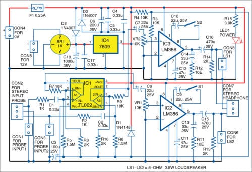
The circuit diagram of the dual-channel audio tracer and tester is shown in Fig. 1. It is built around dual-operational amplifier TL062 (IC1), two LM386 power amplifiers (IC2 and IC3), 9V voltage regulator 7809 (IC4) and a few other components.
The circuit is a simple and effective dual-channel audio troubleshooting tool that works with stereo headphones or two loudspeakers with resistances above 8-ohms. It can also be used in large acoustical systems.
The circuit is basically two-channel audio amplifier. Input stages of both the amplifiers are built around a dual-operational amplifier TL062. You can also use a different operational amplifier with JFET inputs, such as TL072 or TL082 having higher power supply current.
Input resistances of both the channels are fixed by resistors R5 and R6, which are 1.5-mega-ohm each. This is good enough for checking most audio circuits, microphones, acoustical sensors and cables. You can increase the input resistance to more than 10-mega-ohm.
Gain of the first stage of each channel is set to 10, as per relationships given below.
Gain of first stage, Av1=1+R7/R8=10
Gain of second stage, Av2=1+ R9/R10=10
Output stages are built around two LM386 low-power audio amplifiers (IC2 and IC3). Both the audio channels are independent and may be used for different purposes.
Gain of each power amplifier can be set independently using switches S1 and S2. If you open both the switches, gain of the corresponding amplifier will be 20. If you close both the switches, gain of the corresponding amplifier will be 200.
Output connectors CON6 and CON8 are used for external loudspeakers or external acoustical systems. CON7 is used for external stereo headphones. If you use stereo headphones, you must pay attention to the maximum output power so as to not damage the headphones and your ears. Volume of both the channels is adjusted independently with potentiometers VR1 and VR2, respectively.
Power supply. A 9V DC power supply at CON4 is used to power the circuit. A 12V to 20V AC or DC power supply can also be used at CON5. Bridge rectifier BR1 and voltage regulator 7809 are used to convert AC input to 9V DC output. If power supply is available at CON4, do not apply any voltage at CON5.
The circuit will also work with a 12V dry or rechargeable battery connected to CON5. The power supply range decides the output power of LM386.
Download PCB and Component Layout PDFs: click here
Construction and testing
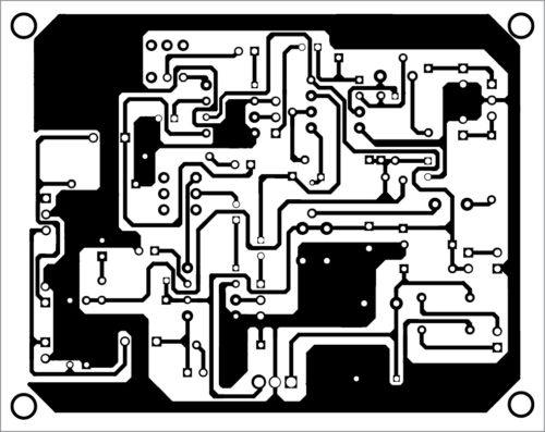
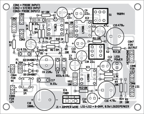
 A PCB layout of the universal audio signal tracer is shown in Fig. 2 and its components layout in Fig. 3. Assemble the components as per the circuit diagram on the PCB. Connect 9V DC to the circuit. The glowing of LED1 indicates the presence of a power supply in the circuit.
Connect any of the inputs (CON1-CON3) to an audio source. Adjust VR1 and VR2 until you get comfortable sound levels at outputs (loudspeaker or headphones).
To use as simple audio signal tracer, connect any of the loudspeakers at CON6 or CON8, or headphones at CON7. Then, connect an audio probe to either CON1 or CON3. You can also use a stereo audio jack at CON2 and headphones at CON7 to perform various tests and troubleshooting in audio equipment.
Petre Tzv Petrov was a researcher and assistant professor at Technical University of Sofia, Bulgaria, and expert-lecturer at OFPPT, Casablanca, Kingdom of Morocco. He is currently working as an electronics engineer in the private sector in Bulgaria