 Most table lamps available in the market do not provide sufficient light to read small-size letters and fonts, especially those found on electronic components. This 20-watt chip-on board (COB) LED table lamp gives sufficient light of about 270 lumens brightness. Each COB actually has several LED (light emitting diode) chips mounted together on the same substrate, which is often ceramic or metal.
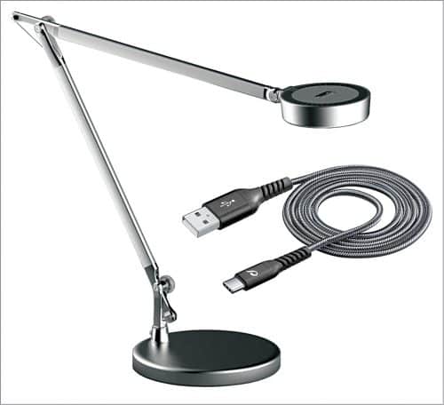
The lamp can be plugged in to any 5V USB adaptor or mobile charger, has light dimmer control, and can replace the circuit in an existing LED fixture. The proposed enclosure for the USB 20W COB LED table lamp is shown in Fig. 1.
Circuit and description
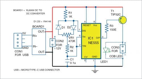
Circuit diagram of USB 20W COB LED table lamp is shown in Fig. 2. The circuit includes a COB LED (LED1), 555 timer IC1, TIP32C power transistor T1, signal diodes D1 and D2, and XL6009 DC-DC converter/booster module.
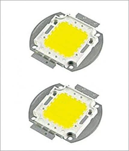
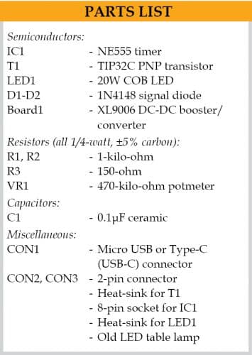
COB LEDs (Fig. 3) are powerful yet quite handy for making LED lights. Most COB LEDs come with heat-sink and are ready to use. You just need a suitable driver and a pair of wires.
COB manufacturers release data sheets for their products that dictate each unit’s specifications as well as minimum, typical, and maximum values for a number of different variables. A few examples of a COB’s characteristics that can be found in the data sheet include colour temperature, typical forward voltage, maximum current, temperature, luminous flux, and relative spectral distribution.
There are different types of COB LEDs, and any suitable type can be used in the circuit. You may refer to ‘Choosing The Right COB LED’ article.
555 timer IC is configured in an astable mode with pulse-width modulation (PWM) control. Potmeter VR1 (470-kilo-ohm) is used to control the brightness of the COB LED through diodes D1 and D2.
TIP32C power transistor is a 3-pin TO-220 plastic-package PNP transistor. It is used to drive the COB LED. It can drive a collector current up to 3A and has a maximum junction temperature up to 150°C. It is recommended to use a suitable heat-sink with it.
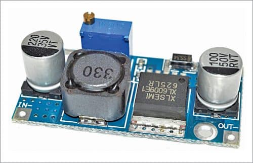
XL6009 booster module. This DC-DC converter/booster module can accept wide input range from 3V to 32V and produce output from 5V to 35V. It has an inbuilt potentiometer to control and adjust the output voltage. This module is a non-isolated step-up (boost) voltage converter featuring adjustable output voltage and high efficiency. The IN+ and IN- are inputs for positive and negative, OUT+ and OUT- are outputs for positive and negative, respectively. The XL6009 module used in the project is shown in Fig. 4.
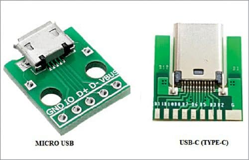
The main advantage of this circuit is that you can connect it with any USB 5V DC mobile charger. You can connect a 5V DC to input terminals (IN+ and IN-) of XL6009 module through micro USB or type-C USB connector. Many breakout boards for micro and Type-C USB are available in the market (Fig. 5). Depending on your charger, you can use any of these breakout boards.
With an input of 5V at CON1, adjust the output across OUT+ and OUT- terminals to 12V using the inbuilt potmeter of XL6009 module and a voltmeter. Then connect the OUT+ and OUT- terminals to CON2 connector of the circuit.
Working of the circuit is straightforward. After connecting the 12V DC supply to CON2, COB LED will glow. Vary VR1 to adjust the brightness.
Construction and testing
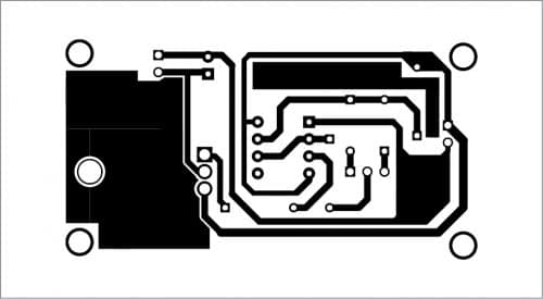
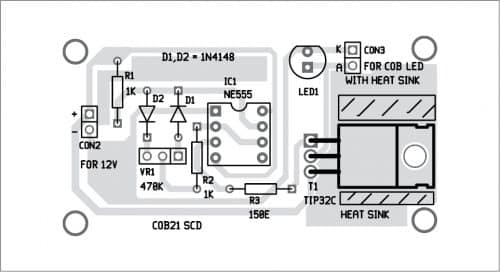
You can assemble the circuit on a general-purpose PCB or a custom designed PCB shown in Fig. 6 and Fig. 7. Use an 8-pin socket for IC1 and suitable heat-sink for power transistor T1. After mounting the components on the PCB, enclose the assembly in a suitable box.
Download PCB and Component Layout PDFs: click here
-Open the base cover of your existing old table lamp. Remove the old inbuilt circuit and replace it with your circuit. Carefully remove the old LED and replace it with the COB LED. Connect the circuit to power supply using any mobile charger or 5V DC power supply.
This COB LED lamp is suitable not only as a table lamp, it gives sufficient light for a small bedroom.
Sani Theo is an electronics enthusiast and technical editor at EFY
Please note: If you are unable to download the source code, please try to open the page in incognito mode and retry or temporarily turn off the antivirus before downloading.


