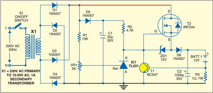
 This transformer-based versatile battery charger circuit can be used to charge any battery, provided the transformer rating is higher than the battery rating. Normally, a linear regulator IC is used for charging. But this charger circuit uses a MOSFET switch, which effectively draws current from the transformer when its voltage is close to the desired battery charging voltage.
The full-wave bridge rectifier rectifies the transformer output and the combination of diode D5 and capacitor C1 provides gate bias voltage to the MOSFET (T2). Zener diode ZD1 maintains the gate voltage at a maximum of 12V relative to the source. The rectified AC potential is also divided by the combination of resistor R1 and 5-kilo-ohm preset VR1 to set the charging voltage.

When the rectified AC voltage is below the threshold of IC1 (TL431), the MOSFET conducts. Filter capacitor C2 at its output charges through diode D6. As the rectified voltage decreases from peak to 0V, IC1 turns off at approximately 13.6V. Transistor T1 conducts to provide another pulse current to charge capacitor C2. Thus power drain from the transformer occurs in short pulses and the battery charges between the pulses.
To limit the charging current to the battery, the current through the battery is sensed by resistor R3. Once the voltage drop across R3 reaches the base-emitter threshold of transistor T1, it conducts to turn on IC1, which, in turn, switches off MOSFET T2. This process continues, limiting the charging current to the battery.


I see versatility as a circuit that can handle a WIDE voltage range.. For example… a 24 volt battery… a 36 volt golf cart battery array… a 48 volt golf cart battery array… this is a ruze
The versatility of the circuit lies in the voltage controller and transformer. With this circuit, you can charge a 12V, 24V, 36V, or 48V battery by changing the transformer rating which should be greater than the battery under charge (BUC). Normally, the output voltage across the transformer should be 10 percent more than the voltage of BUC. In this example as shown, BUC is 12V lead-acid battery, transformer output across the capacitor is around 16V(i.e.Vpeak=√2 Vrms=1.414×12=16V). You can control the charging voltage using preset VR1. You can also charge the 12V BUC using a transformer with higher voltage rating by adjusting VR1 at 13.6V.
BC 547 gets faulty or shorted while testing everytime…why?
Can you please help?
Use a 10K resistor at the base of transistor and also check proper polarity
HI, Som Prasad,
use 100 e resistor in series to base of t1 if you put 10k yuor cut off will not work use CL100 or CTC880 for t 1 in my experience i have noticed the failure of bc547 in these areas.
Sambath kumar.