


 You can use this versatile probe for continuity testing and identification of transistor type and transformer windings. The N-side or P-side of a transistor can be identified quickly in one go. You can make two contacts with the probe in one hand while the other hand is free.
A versatile probe circuit
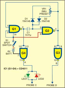
Here is the circuit of the probe. The operation of the circuit is simple. It is driven by an alternating current flowing through two LEDs (LED1 and LED2). So one LED corresponds to forward direction of current flow, while the other shows the reverse direction of current flow. This helps to detect the orientation of the p-n junction with respect to the probes. The LEDs can be arranged near the probes to glow either for the p-side or the n-side as per your choice.
The frequency is determined by capacitor C1 and preset VR1 connected between gates G1 and G2. The frequency can be varied using preset VR1. Higher frequency results in more sensitivity to inductive reactance. The preset is trimmed so that when the probes are shorted, both the LEDs glow equally.

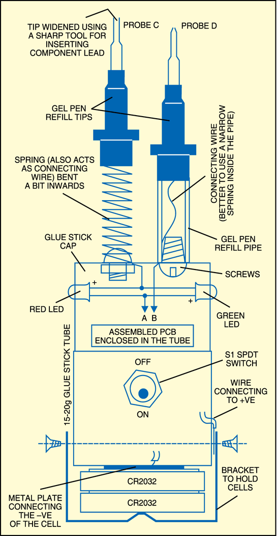
Above is the probe arrangement for testing. Most of the battery power is consumed only when the LEDs glow. The probes have been constructed to provide a good grip on the components under testing. One probe’s tip has been widened. (Drop the empty refill of a ball-pen from some height to remove the ball, then insert a sharp needle or something similar into the tip. Slowly push the needle inside and widen the tip so that a component lead can be inserted into it during testing.) Slightly unequal probe lengths help to make easy contacts.
Construction & testing
Assemble the circuit on a general-purpose PCB which is as compact as possible and put it inside a glue stick tube (whose inner mechanism has been removed) at its centre. The metallic disk and metallic strips can be cut out from any tin container. For the probes, use the spring mechanism of gel ball pens. Probes C and D are the points representing the probe terminals. Two button cells (CR2032) are used to power the probe circuit.

The project was first published in February 2010 and has recently been updated.
