


Presented here is a simple counter circuit that counts the number of visitors entering or exiting an auditorium or any other place where you have installed this circuit at the gates. On receiving an interrupt from light-dependent resistor (LDR) sensors, the counter circuit increments the count and shows it on a 7-segment display.
With these units installed at the entrance and exit gates, you can calculate the number of visitors present in the room by subtracting the count at the exit gate from the count at the entrance gate. The system should be installed on a door such that only one person can cross through at a time, interrupting the light falling on the LDR sensor.

Counter circuit
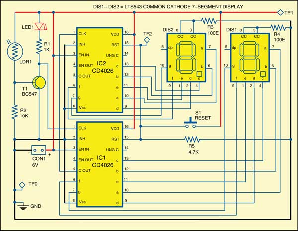
The circuit is built around popular CD4026 counter ICs (IC1 and IC2), light-dependent resistor (LDR1), transistor BC547 (T1), common-cathode seven-segment displays (DIS1 and DIS2) and a few other components. The advantage of using CD4026 counter IC is that it drives a 7-segment display without the need of a driver IC.
Working
The resistance of LDR1 decreases when the intensity of light falling on it increases and vice versa. In dark or absence of light, the LDR exhibits a resistance in the range of mega-ohms, which decreases to a few hundred ohms in presence of bright light.

In this circuit, the amount of light falling on LDR1 decreases as a person crosses the entrance/exit gate and his shadow falls on LDR1. Consequently, the resistance of LDR1 increases to provide a clock pulse to pin 1 of IC1 through transistor T1. During this time, LED1 stops glowing momentarily, indicating that someone is entering or exiting the hall.

IC1 consists of a Johnson decade counter and an output decoder that converts the Johnson code into a 7-segment decoded output for driving one stage in a numerical display. When it receives a clock at pin 1, it advances the count on display DIS1 by ‘one.’ Similarly, the count on the display advances by ‘one’ with each person entering through the gate. When the count reaches ‘9,’ one cycle completes.
Connections
Carry-out pin 5 of IC1 is connected to clock pin 1 of IC2 to cascade another counter. On the next clock after count ‘9,’ it goes high to provide a clock pulse to IC2, advancing its counter by one. Now IC1 starts all over again.
DIS1 shows the unit’s digit and DIS2 shows the ten’s digit of the count. After completion of each cycle, ten’s digit advances by one. You can add more CD4026 counters with 7-segment displays for further extending the display to three digits, four digits, etc. For this, you have to connect carry-out pin 5 of each CD4026 to clock pin 1 of the next CD4026 as shown in the circuit diagram. Pin 15 of both IC1 and IC2 are connected to ground through resistor R5. A reset switch (S1) is connected to 6V for resetting the display to ‘00.’
Download PCB and component layout PDFs: click here
Counter circuit construction and testing
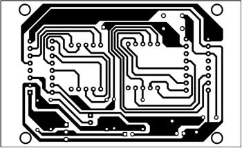
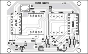
An actual-size, single-side PCB for the visitor counter is shown in Fig. 2 and its component layout in Fig. 3. After assembling the circuit on a PCB, enclose it in a suitable case. Fix LED1, DIS1 and DIS2 on the front panel. Use a two-pin connector for connecting the power supply to the PCB.
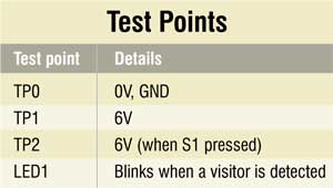
This is a simple circuit and should work immediately after assembly. To check the circuit for proper functioning, verify voltage levels on various test points as per the test point table.
Proper installation is very important. Mount LDR1 on the gate such that light falling on it is interrupted when somebody passes through the gate. We have used a fixed resistor here but, if necessary, you can use a preset in place of R2 for tuning the system to your environment.
The author is a hobbyist and M.Tech from Banaras Hindu University (BHU)


Comment: please help me I made this project properly as you show us bt it cann’t work it steal display zero in all condition. plz help me I must submit it on thursday! thank you!
Sr pl sent me components list of visitors counter
I have tried to print this pcb layout but now my problem is the components layout is deferent when i place it to PCB now Im having problem if this project will work cause the components side is deferent?
This layout wrong
This PCB layout is opposite. The IC pins are opposite in layout that’s why this is not worked.
The PCB layout is correct but if you want to transfer the PCB tracks to copper sheet directly, first you need to flip/mirror the solder side PCB layout while taking its printout.
Has anyone tried to run a simulation? On which software should i try to simulate it?
Sir now I’m pursuing diploma in 6th semester and I want to make electric bike by using bicycle in project. So sir please give me some suggestions
hello, id like to use this counter triggered by an momentary closed condition for use as a lap counter. A NO reed switch triggered by the vehicle’s magnet would be preferred over an IR for my situation. Any thoughts as this should be a fairly easy modification?
Thanks!
what is Background problem?
This is very nice and plzz send me a working video
y did u use that specific capacitor and ic
I built this project but it displays 00 even after I interrupted the pulse. When interrupted the TSOP1738 gives a 1V pulse ON pin 1 of CD4033 but no change in display. It appears to me that the 1V is too small to make the thing work. I used a higher voltage 2.5V and it started to count. What can make the TSOP1738 give out a higher voltage than 1V.
im doint it by using IR sensor and 555 timer in monostable mode. Can you plc share .sch file of circuit made by you. Im week at PCB design. I have Eagle installed in my pc. it will be helpful to design pcb for me
Dear Suyog,
Circuit is designed gEDA,so this ,sch file is not suitable for Eagle. So refer the circuit
and first design its circuit diagram.
Once you have your schematic all ready to convert to PCB. As displayed below you
access file>switch to board, it will then prompt to create a new board from the schematic for
you, click “yes”.
Regards