Most electronic and electric devices require a voltage within certain limits. If the voltage applied is higher than normal, the current drawn by the circuit may exceed the rated value and damage the circuit. If the voltage is too low, the device may not function properly.
In the case of a refrigerator or an air-conditioner, the compressor may not work and could lead to burning of the motor. Additionally, all devices that use compressors, such as refrigerators and air-conditioners, should be restarted after a gap of two to three minutes. Otherwise, the compressor, which is full of refrigerant, may not be able to rotate and may get burnt out by drawing excessive current.
POC Video Tutorial In English
POC Video Tutorial In Hindi
The Voltage Protection Circuit described below cuts out power to the load if the input voltage is too high or too low. The voltage at which the power is cut off can be adjusted. If the power fails briefly and resumes, it switches on power to the load after a gap of a few minutes; this time can be adjusted. If the voltage becomes too high or too low and then normalises, the device switches on after a gap of a few minutes.

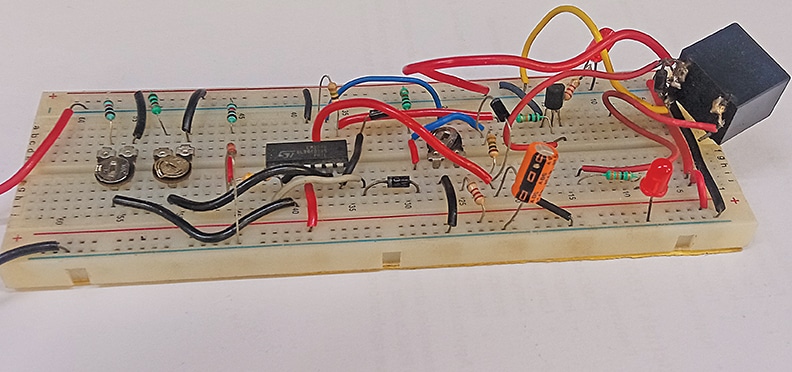
Fig. 1 shows the EFY lab’s prototype on a breadboard.
| Parts List | |
| Semiconductors: | |
| IC1 | -LM324, op-amp |
| T1 | -2N3904 npn transistor |
| D1-D4 | -1N4007 rectifier diode |
| LED1, LED2 | -5mm LED (green, red) |
| ZD1 | -6V zener diode |
| Resistors (all 1/4-watt, ±5% carbon):R1, R7, R8, | |
| R10, R11 | -1-kilo-ohm |
| R2 | -4.7-kilo-ohm |
| R3, R9 | -10-kilo-ohm |
| R4, R6 | -1-mega-ohm |
| R5 | -2.2-kilo-ohm |
| VR1, VR2 | -10-kilo-ohm preset |
| VR3 | -5-kilo-ohm preset |
| Capacitors: | |
| C1 | -100µF, 35V electrolytic |
| Miscellaneous: | |
| RL1 | -12V SPDT relay |
| CON1-CON3 | -2-pin connector |
| -15V unregulated power supply | |
| -230V AC appliance as load | |
Voltage Protection Circuit with Adjustable Delay – Circuit and Working
The circuit diagram of the voltage cut out with delay is shown in Fig. 2. It is built around quad op-amp LM324 (IC2), transistor 2N3904 (T1), 12V SPDT relay, three 1N4007 diodes, and a few other components.

The heart of the circuit is the quad op-amp IC LM324. This IC has four op-amps, but only three are used in the circuit. The non-inverting input (pin 5) of one op-amp (built around IC1B) is connected to a reference voltage, which is the voltage of the Zener diode, through R2.
Unregulated voltage is applied to the inverting input (pin 6) through preset VR1. If the supply voltage is too high, the voltage at the inverting input is more than the reference voltage at the non-inverting input, and the output of the comparator is low.
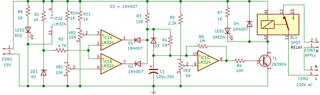
Similarly, the output voltage of the second op-amp (built around IC1A) is low if the input voltage is low. In this case, the unregulated voltage applied at the inverting input is lower than the reference voltage at the non-inverting input. The outputs of the two comparators are sent to the AND gate consisting of diodes D1 and D2 and pull-up resistor R3. The output is high only if both the inputs are high, that is when the input voltage is within the preset limits.
The output voltage is used to charge capacitor C1. When the voltage on the capacitor is more than the voltage applied to the non-inverting input of the third op-amp (built around IC1C) through VR3 and R5, the output of the op-amp goes high and switches on the relay. The time delay can be adjusted by varying the preset VR3. Diode D3 is used to discharge capacitor C1 when the power is off or beyond set limits.
Red LED2 is used as the power-on indicator and green LED1 lights up when the relay is energised, and the input voltage is within limits. The circuit requires an unregulated power supply, which can be obtained from a 0-15V, 500mA transformer, rectifier, and a filter (not shown in Fig. 2).
Also Check: Overvoltage and Undervoltage Protection Circuit
Construction and Testing
As the circuit is simple, it can be assembled on a general-purpose PCB or on a breadboard, like the prototype shown in Fig. 1. After assembling the circuit, enclose it in a suitable box. Before operating the circuit, it should be aligned/setup as follows.
Alignment: The circuit can be aligned either by using a variable DC power supply or a Variac. VR1 is used to adjust the upper limit and VR2 to adjust the lower limit of the voltage at which the supply to the load is shut off. Another method of adjusting the circuit is to set the voltage at the wiper of VR1 (high cut) at 1 to 1.5 volts below the Zener voltage and the wiper of VR2 (low cut) at 1 to 1.5 volts below the Zener voltage, with the input at normal voltage.
For adjusting the time delay, a voltage within the set limits should be applied, and when a time equal to the delay required has passed, VR3 should be adjusted until LED1 is on and the relay energises. The resistor through which C1 is charged is not adjusted; only the preset which applies voltage to the inverting input of the op-amp (built around IC1C) is adjusted, making alignment easier. In this way, the rate at which the capacitor charges is independent of the time setting obtained by adjusting VR3.
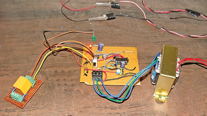
The author’s prototype made on a general-purpose PCB is shown in Fig. 3. This prototype also includes an unregulated power supply, which is obtained from a 0-15V, 500mA transformer, rectifier, and a filter.
EFY Note: The circuit is not of a voltage stabiliser. If the supply remains either high or low for a long period, a voltage stabiliser should be used. Of course, this circuit can be used along with a stabiliser, and it will cut off power to the load if the voltage is too high or too low and not within the limits even when a stabiliser is used. It will also provide a delay, which is not provided by most stabilisers.
Pradeep Vasudeva is a member of the Indian Forest Service, presently posted as Additional Principal Chief Conservator of Forests (Working Plan) Jabalpur. Electronics has been his passion since adolescence, and his areas of interest include amateur radio, RF circuits, and audio projects.