


 Polling by electronic voting machines (EVMs) has become a norm during elections. Unlike paper ballot systems, EVMs are safe and reliable as these rule out the possibility of invalid voting. These are more economical and efficient too. Their compact size saves transportation costs.
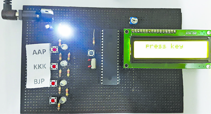
Here we describe the design of an electronic voting machine based on ATmega16A microcontroller. To cast a vote, users need to press the key against the name of the candidate of their choice. The vote is automatically saved in the microcontroller, and simultaneously the LCD shows the message “Thank You.” The author’s prototype is shown in Fig. 1.
Circuit and working
As shown in Fig. 2, the circuit of the electronic voting machine is built around ATmega16A microcontroller (IC2), IC 7805 (IC1), a 16×2 LCD (LCD1) and other associated components.

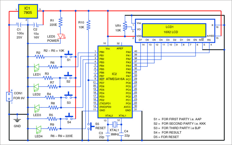
The controller used here operates off 5V DC supply. So a 7805 voltage regulator IC is used to step 9V DC down to 5V. Capacitors C1 and C2 are used to reduce ripples. ATmega16A has 32 general purpose input/output (I/O) pins. An external 8MHz crystal oscillator is used to provide the timing pulse. Four switches (S1 through S4) are connected to Port B (PB0, PB1, PB2 and PB3) of IC2.
The LCD (LCD1) operates in 4-bit mode. Its data pins (D4, D5, D6 and D7) are connected to Port A (PA2, PA3, PA4 and PA5) of IC2. Control pins RS and EN are connected to pins PA0 and PA1 of IC2, respectively.

The LCD displays each character in a 5×7 pixel matrix. You can adjust the contrast of the LCD using a 10-kilo-ohm preset. While programming ATmega16A, note the fuse bit settings. Low fuse bit value is E4 and high fuse bit value is D9.
Construction and testing
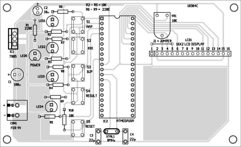
An actual-size PCB layout for the voting machine using AVR is shown in Fig. 3 and its components layout in Fig. 4.
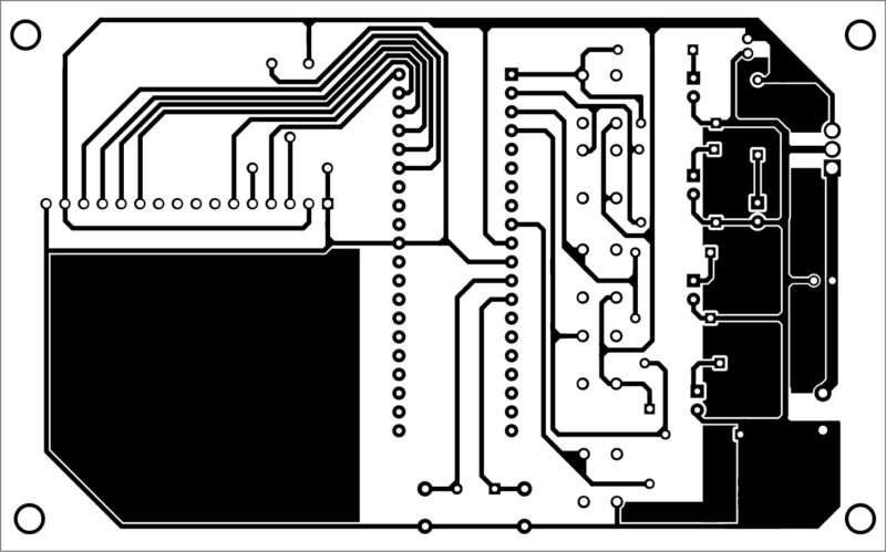
Download PCB and component layout PDFs: click here
Connect LCD1 to the PCB as shown in the figure. Now, mount all the switches (S1 through S5) and LED1 through LED5 on the front panel of this cabinet.
Software
The software is written in ‘C’ language and compiled using Keil software. You can use any suitable software for programming the ATmega16A microcontroller. ProgISP programmer was used for programming at EFY Lab.
Download source code
Assembly and testing
After assembling the circuit on the PCB, check it for proper connections. Now, burn the program (voting code.hex) into the microcontroller using the programmer. Insert the microcontroller into the IC base and connect 9V battery. LCD1 will show “press any key” message.
This circuit has provision to cast votes for three candidates as it uses switches corresponding to three candidates only (S1 for AAP, S2 for KKK and S3 for BJP). Switch S4 is pressed to calculate the results.
When you press any of switches S1 through S3, the corresponding pin of the microcontroller gets pulled up to Vcc and it operates as per the programmed logic. The LCD1 will show a “Thank you” message. The respective LED (LED1-LED3) must glow to indicate that voting is successful.
Press switch S4 to get results like the winner and its share of the votes. In case two or more parties get equal votes, press switch S4 again to get further details.


you have to upload project report..
Can you please share a complete project on my mail id.
Hello, assist me with the programming code of AVR machine using Atmega 16A please
Dear Anthony,
There are several ways to program AVR microcontrollers. You can program Atmega 16 using ISP programer. The software is written in ‘C’ language and compiled using Keil software. You can use any suitable software for programming the ATmega16A microcontroller. ProgISP programmer can be used for programming.
First of install ProgISP from internet. After successfully installation follow the steps to burn (program) the code into Atmega ICs using ProgISP programmer :
1. Installing ProgISP.
2. Save source code in hex code .
3. Open ISP programmer.
4. Select IC here Atemgea 16A and insert the IC in zip socket
5. Upload the hexcode.
6. Now window shows uploded succesfuly.
7. Now remove and use for the project.