


 Many a time we forget to switch off the motor pushing water into the overhead tank (OHT) in our households. As a result, water keeps overflowing until we notice the overflow and switch the pump off. As the OHT is usually kept on the topmost floor, it is cumbersome to go up frequently to check the water level in the OHT. Presented here is a microcontroller based water level controller cum motor protector to solve this problem.
It controls ‘on’ and ‘off ’ conditions of the motor depending upon the level of water in the tank. The status is displayed on an LCD module. The circuit also protects the motor from high voltages, low voltages, fluctuations of mains power and dry running.
Circuit description
![]()

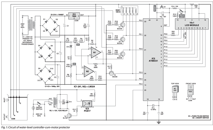
Fig. 1 shows the circuit of the microcontroller-based water level controller-cum-motor protector. It comprises operational amplifier LM324, microcontroller AT89C51, optocoupler PC817, regulator 7805, LCD module and a few discrete components.
The AT89C51 (IC2) is an 8-bit microcontroller with four ports (32 I/O lines), two 16-bit timers/ counters, on-chip oscillator and clock circuitry. Eight pins of port-1 and three pins of port-3 are interfaced with data and control lines of the LCD module. Pins P3.0, P3.1 and P3.6 are connected to RS (pin 4), R/W (pin 5) and E (pin 6) of the LCD, respectively. Pin EA (pin 31) is strapped to Vcc for internal program executions. Switch S2 is used for backlight of the LCD module.
Power-on-reset is achieved by connecting capacitor C8 and resistor R14 to pin 9 of the microcontroller. Switch S1 is used for manual reset.
The microcontroller is operated with a 12MHz crystal. Port pins P2.0 through P2.2 are used to sense the water level, while pins P2.3 and P2.4 are used to sense the under-voltage and over-voltage, respectively. Pin P3.4 is used to control relay RL1 with the help of optocoupler IC3 and transistor T5 in the case of under-voltage, over-voltage and different water level conditions. Relay RL1 operates off a 12V supply. Using switch S3, you can manually switch on the motor.
The LM324 (IC1) is a quad operational amplifier (op-amp). Two of its op-amps are used as comparators to detect under- and over-voltage. In normal condition, output pin 7 of IC1 is low, making pin P2.3 of IC2 high. When the voltage at pin 6 of N1 goes below the set reference voltage at pin 5 (say, 170 volts), output pin 7 of N1 goes high. This high output makes pin P2.3 of IC2 low, which is sensed by the microcontroller and the LCD module shows ‘low voltage.’
In normal condition, pin 1 of N2 is high. When the voltage at pin 2 of N2 goes above the set voltage at pin 3, output pin 1 of N2 goes low. This low signal is sensed by the microcontroller and the LCD module shows ‘high voltage.’
Presets VR1 and VR2 are used for calibrating the circuit for under-and over-voltage, respectively.
The AC mains is stepped down by transformer X1 to deliver a secondary output of 12V at 500 mA. The transformer output is rectified by a full-wave bridge rectifier comprising diodes D5 through D8, filtered by capacitor C2, and used for the under- and over-voltage detection circuitry.
The transformer output is also rectified by a full-wave bridge rectifier comprising diodes D1 through D4, filtered by capacitor C1 and regulated by IC4 to deliver regulated 5V for the circuit.
When water in the tank rises to come in contact with the sensor, the base of transistor BC548 goes high. This high signal drives transistor BC548 into saturation and its collector goes low. The low signal is sensed by port pins of microcontroller IC2 to detect empty tank, dry sump and full tank, respectively.
An actual size, single-side PCB for the water level controller-cum-motor protector (Fig. 1) is shown in Fig. 2 (View PDF) and its component layout in Fig. 3 (View PDF).
Download PCB and component layout PDFs (Fig. 2, 3): click here
Operation
When water in the tank is below sensor A, the motor will switch on to fill water in the tank. The LCD module will show ‘motor on.’ The controller is programmed for a 10-minute time interval to check the dry-run condition of the motor. If water reaches sensor B within 10 minutes, the microcontroller comes out of the dry-run condition and allows the motor to keep pushing water in the tank.
The motor will remain ‘on’ until water reaches sensor C. Then it will stop automatically and the microcontroller will go into the standby mode. The LCD module will show ‘tank full’ followed by ‘standby mode’ after a few seconds. The ‘standby mode’ message is displayed until water in the tank goes below sensor A.
In case water does not reach sensor B within 10 minutes, the microcontroller will go into the dry-running mode and stop the motor for 5 minutes, allowing it to cool down. The LCD module will show ‘dry-sump1.’
After five minutes, the microcontroller will again switch on the motor for 10 minutes and check the status at sensor B. If water is still below sensor B, it will go into the dry-running mode and the LCD module will show ‘dry-sump2.’
The same procedure will repeat, and if the dry-run condition still persists, the display will show ‘dry-sump3’ and the microcontroller will not start the motor automatically. Now you have to check the line for water and manually reset the microcontroller to start operation.
In the whole procedure, the microcontroller checks for high and low voltages. For example, when the voltage is high, it will scan for about two seconds to check whether it is a fluctuation. If the voltage remains high after two seconds, the microcontroller will halt running of the motor. Now it will wait for the voltage to settle down. After the voltage becomes normal, it will still check for 90 seconds whether the voltage is normal or not. After normal condition, it will go in the standby mode and start the aforementioned procedure.
Practical applications
This controller is useful for single-phase operated motor-pumps and the pumps that suck water from the ground water tank. A small push-to-off manual switch in series with sensor A can also make it useful for pumps that suck water from Jal Board’s supply. Because of the particular timing of this water supply, the controller must be switched on within the timing of the water supply and switched off when water is not being supplied.
When the controller is ‘on’ during the supply timings, it will wait for the tank to get empty before starting the motor. However, you can also start the motor using the pushbutton. The motor will turn on ignoring the status of the water level and will go through the aforementioned procedure.
Sensor positions in the tank
Four non-corrosive metallic sensors are installed in the tank as shown in Fig. 1. Sensor COM is connected to Vcc supply from the circuit. Sensor A detects the empty tank to start the motor. Sensor B detects dry-running condition of the motor and sensor C detects the full tank to stop the motor. Make sure that sensor B is around 2 cm above sensor A to check the dry-running condition properly.
Calibration
Care must be taken when calibrating for under-voltage and over-voltage. Always calibrate when the relay is in ‘on’ position. If you calibrate in the standby mode, it will trip at a voltage nearly 10 volts lower than the set voltage due to the loading effect.
Software
The source code is written in Assembly language and assembled using 8051 cross-assembler. The generated Intel hex code is burnt into microcontroller AT89C51 using a suitable programmer. The software is well-commented and easy to understand. All the messages are displayed on the LCD module.

Can you please send the .c code to mail ID
I want buy this empty PCB
PCB is not in stock right now.
Thanks for the full project, this is really very helpful.
But i have a suggestion to make it more practical to use in our homes.
Please make it wireless using RF wireless modules as they are very cheap and divide this project in two parts, transmitter and receiver.
Since most of the time our OHT are at 3rd, 4th or even higher floors so running that much wire for sensors is not practical and costly, so making it wireless will solve this problem.
This system should also show real time water level indication from 0% to 100% and having 10% distance from each point so it will make 10 sensors.
Remove that transformer part as we can use normal 12v chargers laying around in our homes, since using transformer is bit risky too.
Please can I get the C code in my mail?
Thank you.
Hi Eze, the source code is present at the end of the page.
This project was designed using Assembly language and not C language. So C code is not available.