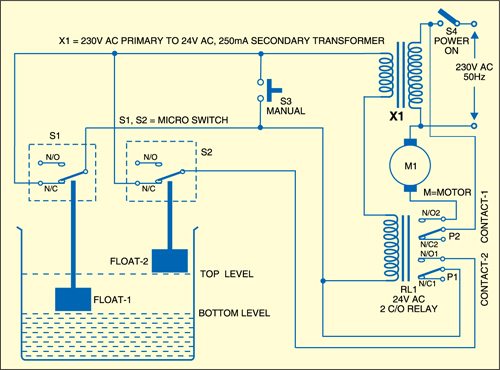
 Here is a simple water pump controller circuit for controlling the water level in an overhead tank. The main components of this pump controller are a step-down transformer, a 24V AC double-changeover relay, two floats and two micro switches.
Water pump controller circuit
Any available relay can be used irrespective of its coil voltage. Of course, the current rating of contacts should be taken into account according to the motor power. The relay should have two contacts. A step-down transformer having secondary voltage suited to the coil voltage of the relay is used. As the circuit works off AC, no rectification is necessary. Micro-switches S1 and S2 fixed on top of the water tank are operated by separate floats: one for sensing the bottom level and the other for the top level. A three-core wire is used for connecting these switches to the relay.

Circuit operation
Working of the circuit is simple. As the water level in the tank goes down to reach the bottom, float-1 releases the moving contact of micro-switch S1, causing the circuit to complete and energise relay RL1. The pump gets power supply through relay contact-1 and starts running. At the same time, relay contact-2 also closes, which provides 24V AC through moving contact of switch S2 connected in the normally-closed (N/C) position.
As the water level rises in the tank, the moving contact of micro-switch S1 is opened by float-1, but the pump continues to run as the circuit completes through switch S2 and relay contact-2.
When the tank is full, the contact of switch S2 is opened by float-2 and the relay de-energises to stop the pump. The pump restarts only when water goes down to the bottom level and the moving contact of switch S1 is released by float-1. This cycle repeats and water level in the tank is controlled automatically.
If the mains power fails when the pump is running, the pump stops. It has to be restarted manually when power resumes. For this purpose, a push-to-on switch is provided. Align float-1 and float-2 such that these touch the moving contacts of switches S1 and S2 when water touches the respective level.
The project was first published in August 2010 and has recently been updated.


I need automatic Water Pump Control circuit
You can check out the automatic Water Pump Control circuit here.