This project is built around an MRF24WBOMA Wi-Fi module, a PIC microcontroller and a camera module using the TCP-IP protocol. The camera captures live video from a remote location, which is transmitted wirelessly through the Internet and can be viewed on a PC or laptop.
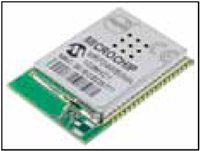
The design uses easily-available low-cost components and a serial peripheral interface (SPI). Microchip’s recently introduced MRF24WBOMA (see Fig. 4) is an inexpensive Wi-Fi chip that uses SPI communication. Block diagram of the Wi-Fi embedded webcam is shown in Fig. 2.
Circuit and working for Wi-Fi Embedded Webcam
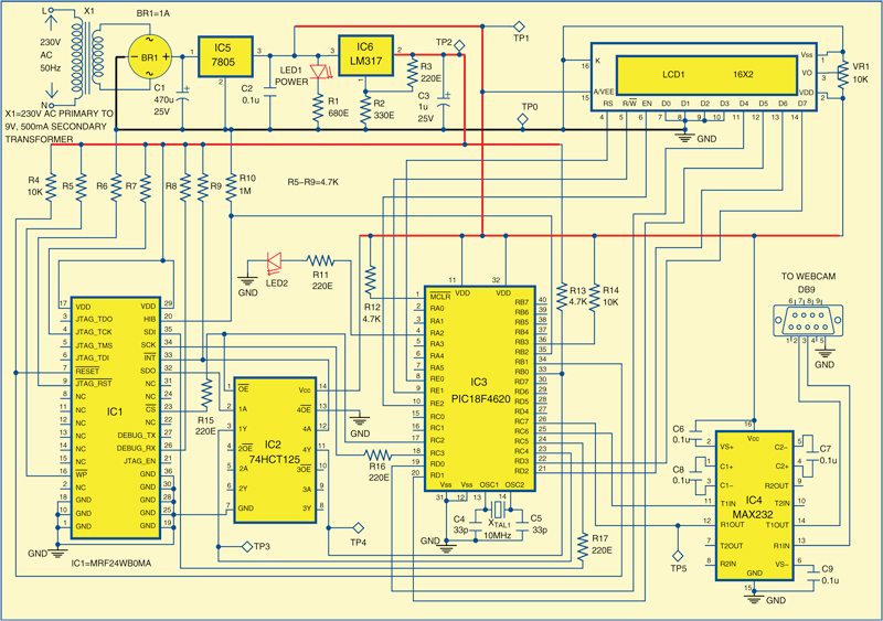
The circuit diagram for MRF24WBOMA-based Wi-Fi embedded webcam is shown in Fig. 3.
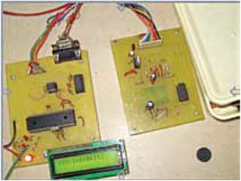
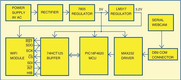
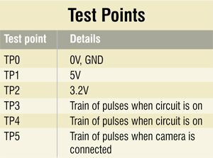
As shown in the block diagram (Fig. 2), the power supply for the circuit includes 9V AC, a rectifier, a 7805 fixed regulator and an LM317 adjustable regulator. This supply drives the main circuit, which includes the Wi-Fi module, the 74HCT125 buffer, the PIC microcontroller and the MAX232 driver.
Power supply
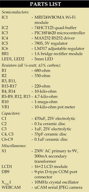
The 9V derived from transformer X1 is rectified by retifier module BR1, filtered by capacitor C1 and given to 7805 IC, which is a fixed 5V regulator. The LM317 adjustable regulator is configured to give a fixed 3.2V meant for the MRF24WBOMA Wi-Fi module. LED1 indicates the presence of power in the circuit.
MRF24WBOMA module
The MRF24WBOMA is a low-power, 2.4GHz, IEEE Std. 802.11-compliant, surface mount module with all associated RF components—crystal oscillator, by-pass and bias passives with integrated MAC, baseband, RF and power amplifier, an built-in hardware support for AES and TKIP. The MRF24WBOMA module is approved for use with the integrated PCB meander antenna. The PCB antenna is fabricated on the top copper layer and covered with solder mask.
The module interfaces to the PIC microcontroller via a serial slave SPI interface for interrupt, hibernate, reset, power and ground signals. The module normally runs on a single supply voltage of 3.3V, though here we have used a 3.2V supply. It also supports optional JTAG and serial debug for testing. The debug port operates at 3.3V and requires a level shifter for operation with RS232 devices.
The MRF24WBOMA module is designed for use with Microchip’s TCP/IP software stack. The software stack has an integrated driver that implements the API, which is used in the module for command and control, and for management data packet traffic. Other details of TCP/IP stack can be found from its data sheet.
Buffer/level shifter
74HCT125 has quadruple bus buffer gates with 3-stage outputs. These gates feature independent line drivers with 3-state outputs. Each output is disabled when the associated output-enable (OE) input is high. To ensure the high-impedance state during power up or power down, OE should be tied to Vcc supply through a pull-up resistor; whose minimum value is determined by current-sinking capability of the driver. The 74HCT125 has been used here as a level-shift interface.
Microcontroller. PIC18F4620 microcontroller, the heart of this project, has features that significantly reduce power consumption during operation. The key features are alternate run modes and multiple idle modes. The SDO and CS pins of Wi-Fi module are connected to microcontroller through the 74HCT125 buffer.
Download PCB and component layout PDFs: click here
Microchip’s PIC18F4620 was selected because it is low-cost and has sufficient memory for coding—64k Flash memory and 4k RAM. It is available in 40-pin DIP package and has a hardware SPI bus. The code has been written using C18 compiler to fit within the memory of PIC18F4620.
LCD module
16×2 LCD module has been used to display the IP address and for debugging the project. It is operated in 4-line mode. Port pins RE0, RE1 and RE2 of the microcontroller are connected to RS, R/W and EN control pins of the LCD, respectively. Port pins RD0, RD1, RD2 and RD3 of the microcontroller are connected to D4, D5, D6 and D7 of the LCD, respectively. Preset VR1 is used to control the contrast of the LCD.
MAX232 driver
MAX232 has four sections: dual charge-pump DC-DC voltage converters, RS232 drivers, RS232 receivers, and receiver and transmitter enable control inputs.
A typical driver output voltage swing is ±8V when loaded with a nominal 5-kilo-ohm RS232 receiver and VCC = +5V. Output swing is guaranteed to meet the EIA/TIA-232E and V.28 specifications.
Pins 25 (RC6/TX) and 26 (RC7/RX) of the microcontroller are connected to pins 11 and 12 of MAX232, respectively. Pins 14 and 13 of MAX232 are connected to pins 2 and 3 of DB9 connector, respectively.
Camera
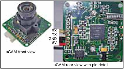
Several camera modules are available in the market. For 5V operation, we chose microCAM (uCAM) serial JPEG camera from 4D Systems (www.4dsystems.com.au) instead of a USB camera to avoid driver-related issues.
The camera is connected to PIC microcontroller through 9-pin DB9 and RS232 level shifter (MAX232). uCAM is a highly integrated serial camera module, which can be attached to any host system that requires a video camera or a JPEG compressed still camera for embedded imaging applications. uCAM comes in a compact form factor with a built-in lens and a 4-wire connector (for 5V, GND, TX and RX) that provides easy access to both power and serial data. It is compatible with C328 JPEG camera. The uCAM used in this project is shown in Fig. 5. You need to connect 5V supply to this camera.
SPI communication
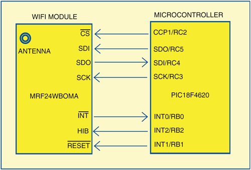
SPI communication with MRF24WBOMA is illustrated in Fig. 6. PIC microcontroller is chosen as master and Wi-Fi as slave. FOSC/64 clock mode is chosen by proper setting of SSPCON1 register of PIC18F4620.
The software
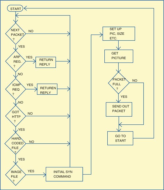
Software for the PIC microcontroller is written in ‘C’ language and compiled using MPLAB IDE. The program flowchart is shown in Fig. 7.
The project is developed using ‘C’ source files such as WF_Spi, ARP, DHCP, ICMP, IP, main, stackTSK, TCPIP, tick, UART, UDP, WF_Config,WF_Eint, WFConnectionAlgorithm, WFConnectionManager, WFConnectionProfile,WFDataTxRx, WFDriverCom, WFDriverRaw, WFEventHandler, WFInit, WFMac, WFMgmtMsg, WFParamMsg, WFPowerSave, WFScan, WFTxPower and xlcd. (All these files are included in this month’s EFY EVD.)
The project is based on communication between the Wi-Fi module, microcontroller, PC and the camera, which are closely controlled through the software. When LED2 starts blinking it indicates that stacking is running and communication is successfully established with remote client PC. This LED2 monitored through timer interrupt is defined in main.c file.
The Wi-Fi driver routines are nothing but routine files from Microchip TCP-IP stack. The ARP, ICMP, UDP and DHCP protocol implementation are all files from Microchip TCP-IP stack. But the TCP protocols are customised routines written in ‘C’ to incorporate camera routines into the memory size of PIC18F4620. The TCP protocol implementation and camera routines are available in IP.c source file only.
Before writing the code note that 10MHz crystal is used as oscillator source and the clock is set at 40 MHz using HSPLL fuse setting through software.
#pragma config OSC=HSPLL, WDT=OFF,
MCLRE=ON, PBADEN=OFF, LVP=OFF
Below some important source program routines used in this project are explained.
SPI communication. SPI communication between PIC and Wi-Fi is initialised by suitable initiation code before starting communication. These instructions are available in WF_Spi.c file as given below.
WF_SPICON1 = 0x30; // SSPEN bit is
set, SPI in master mode, (0x30 is for
FOSC/4),
WF_SPISTATbits.CKE = 0; // Transmit
data on falling edge of clock
WF_SPISTATbits.SMP = 1; // Input
sampled at end? of data output time
After SPI initialisation, Wi-Fi should be initialised for proper network protocol transmission.
Wi-Fi initialisation and other relevant codes are included in the WFMac.c file. The rouines listed below are implemented only after understanding the coding in Microchip TCP-IP Stack.
MACInit () routine. MACInit () routine given below does necessary initialisation of RAW registers in Wi-Fi module.
void MACInit(void)
{
WF_Init();
}
MACInit() calls WF_Init() and RawInit() as given below.
The WFHardwareInit() in WF_Init() is important for proper initialisation.
WF_Init routine is given below:
void WF_Init(void)
{
UINT8 version;
unsigned char LCD1[16];
WFHardwareInit();
RawInit();
WFGetMRF24WB0MVersion(&version);
WF_ASSERT(version >= EXPECTED_
MRF24WB0M_VERSION_NUMBER);
WFEnableMRF24WB0MMode();
WF_LibInitialize();
}
RAWInit() routine is given below:
void RawInit(void)
{
ScratchUnmount(RAW_TX_ID);
ScratchMount(RAW_RX_ID);
ScratchUnmount(RAW_RX_ID);
RawWindowReady[RAW_RX_ID] = FALSE;
g_encPtrRAWId[ENC_RD_PTR_ID] =
RAW_RX_ID;
g_encIndex[ENC_RD_PTR_ID] = BASE_
TCB_ADDR;
RawWindowReady[RAW_TX_ID] = FALSE;
SetRawWindowState(RAW_TX_ID, WF_RAW_
UNMOUNTED);
g_encPtrRAWId[ENC_WT_PTR_ID] = RAW_
INVALID_ID;
g_encIndex[ENC_WT_PTR_ID] = BASE_
TX_ADDR
g_wasDiscarded = TRUE;
g_rxBufferSize = 0;
g_txPacketLength = 0;
g_txBufferFlushed = TRUE;
g_rxIndexSetBeyondBuffer = FALSE;
return dwReturn;
}
Camera interface
The camera should be first connected to PIC microcontroller via serial port. The baud rate can be 14400, 56000, 57600 or 115200, though better synchronisation was obtained at baud rate 56000 during testing. The camera is assigned with dynamic IP address, which is assigned by DHCP client routine rather than fixed IP address. The advantage is that the IP address gets assigned automatically as per local network and we need not assign it manually. DHCP client routine associated with UDP protocol does the necessary task for auto configuration of the IP address.
The camera should be synchronised by issuing sync command until it acknowledges c328syn() routine, which is part of the IP.c file, as listed below. After taking pictures, suitable reset command is issued to camera module for taking fresh pictures. The Reset() routine is also included in the IP.c file for the same.
The sync command is sent as given below:
void c328syn(){
BYTE a[6],i;
char k[6];
s1:
do{
send(C328R_COMMAND_PREFIX);
send(C328R_COMMAND_SYNC);
send(0x00);
send(0x00);
send(0x00);
send(0x00);
DelayMs(10);
}
Download source code for Wi-Fi Embedded Webcam: click here
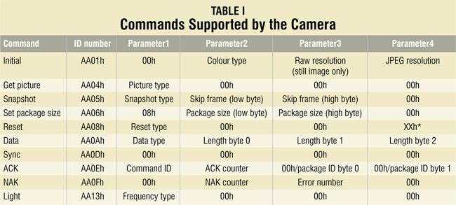
The camera uses ten commands as given in Table I. In the IP.c file you can find various routines for communication with camera including setup(), snap() and getpic(). Camera setup () routine is used for configuring camera for size of the image and light frequency etc. Snap () routine is used to take pictures and getpic () routine is used to retrieve pictures. Get() routine retrieves image data in packets and sends the packets through ENC, packet by packet, until all image data are sent. To display in HTML page we use ne_print () routine.
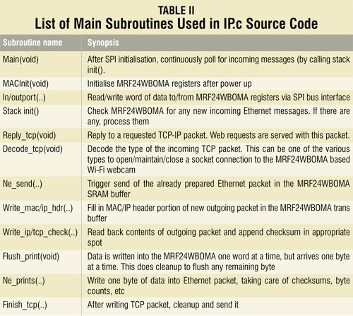
The list of main subroutines used in the IP.c source code is given in Table II.
Construction and testing
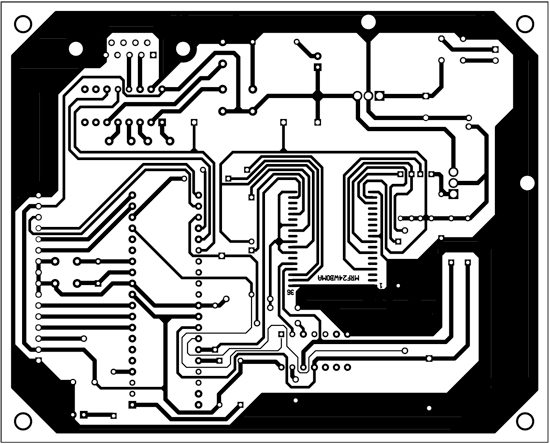
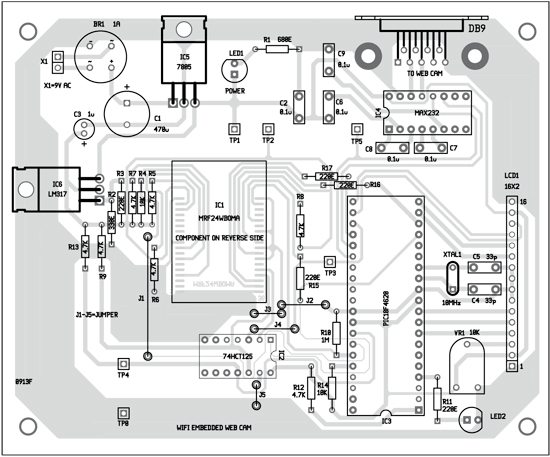
single-side PCB layout of the Wi-Fi embedded system is given in Fig. 8 and its component layout in Fig. 9.
Assemble the components on the PCB and connect power supply to the circuit. Before switching-on the circuit burn the hex code into the microcontroller. You need MPLAB IDE version 8.36.00.00 along with MCCC18 compiler v3.84 for compiling the code and burning the hex code into the microcontroller. Take care of the following:
- PC should be connected to either wireless modem or wireless router with modem. Note that connection between the board and router should be wireless, but the connection between PC and the router should be non-wireless. Hence PC should be connected to Ethernet port of the router.
- The modem or router should be configured as follows:
SSID=kathir, and security=none. If you want to change SSID name, change it in wf_config.h file and compile and program the microcontroller. - Camera should be connected to the board through RS232 cable.
- When you switch-on the circuit, you will see default IP address as 169.254.1.1. Then it will switch over to a new IP address, say, 192.168.43.51, depending on your network. You can see this address on your LCD screen also. Since DHCP client is enabled, you get the correct IP address in LCD display.
- On typing the 192.168.43.51 IP address in address bar of your web browser, a screen will appear with ‘ELECTRONICS FOR YOU’ on top as shown in Fig. 10.
- If you click ‘switch-on’ button, you can see live video being captured by the camera on your PC screen.
Note that, since the processor speed is limited to 40 MHz, we cannot increase camera speed baud rate beyond 57600. Hence we cannot display a smooth live video. You can click ‘switch-off’ button to close the captured image.


Further applications
By careful PORT forwarding of wireless router to local IP address, appliances can be controlled through the webcam from any place in the world. Besides, by using high-speed ARM processors we can increase the camera’s baud rate and thereby display live pictures smoothly by using AJAX in webpage design.
Monitoring of parameters such as temperature, pressure, voltage and current can be done via the Internet from anywhere in the world by connecting suitable sensors to input port of the microcontroller. Since PIC18F4620 has limited memory space, this feature was not included in this article.
The author M. Kathiresan (M.Sc) was a sub-divisional engineer (retd) at mobile services of BSNL, A. Robson Benjamin (M.Sc, Ph.D) is associate professor of physics at American College, Madurai and C. Vijayan (M.Sc, M.Phil) is associate professor of physics at Vellaichamy Nadar College, Madurai


Can I get more details about this project..? For ex: reference video r else documentation….? Can you do it as soon as possible I will wait for your response Thankyou