Here is a simple circuit of wire break alarm that activates after a delay of 15 to 30 seconds. When the thin-wire loop running across the entrance door is broken, the alarm sounds after a delay of 15 to 30 seconds, the time period set through VR1. Thus the occupants get sufficient time to lock the room from the outside and catch the thief.
Wire break alarm circuit
The circuit uses CD4060, which is a 14-stage ripple-carry binary counter/divider and oscillator. It is wired as a timer here and does not need input pulse for trigger. CD4060 gets activated as soon as the power supply is switched on. Output O13 of CD4060 goes high after the lapse of preset delay set through VR1. Transistor SL100 (T2) is wired as a switch to power the timer section built around CD4060. When the wire loop is closed, transistor T2 does not conduct. So power to the timer circuit is not available and the piezobuzzer does not sound.
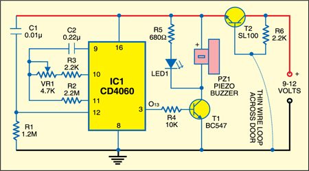
On the other hand, when the wire loop is broken by some intruder, transistor T2 conducts to power the circuit and the piezobuzzer sounds after 15 to 30 seconds. IC1 can be reset by connecting the wire loop or interrupting the supply.

Construction & testing
The circuit works off regulated 9V-12V. Assemble it on a general purpose PCB and enclose in a metallic or plastic box of appropriate size. Connect piezobuzzer PZ1 through external wires and complete the installation.
The article was first published in May 2008 and has recently been updated.