 It is now possible to have a prosthetic body part complete your daily outside works while staying safe inside your home.
What if you had an extra pair of arms to carry out tasks somewhere else while you controlled them from another location. Seems unrealistic, right? Well, no.
In this project, we will learn how to design a prosthetic hand that can replicate natural hand movements and muscle contractions. Although artificial, it works similarly to a biological hand by following the muscle signals. To achieve this, we will try to capture the muscle contraction and stress value and then use those muscle signals to control the prosthetic arm located somewhere else wirelessly. By attaching a prosthetic arm and controlling it using muscle movements, this device can greatly benefit those who are physically challenged.
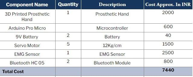
Bill of Materials
Assembly of Prosthetic Hand
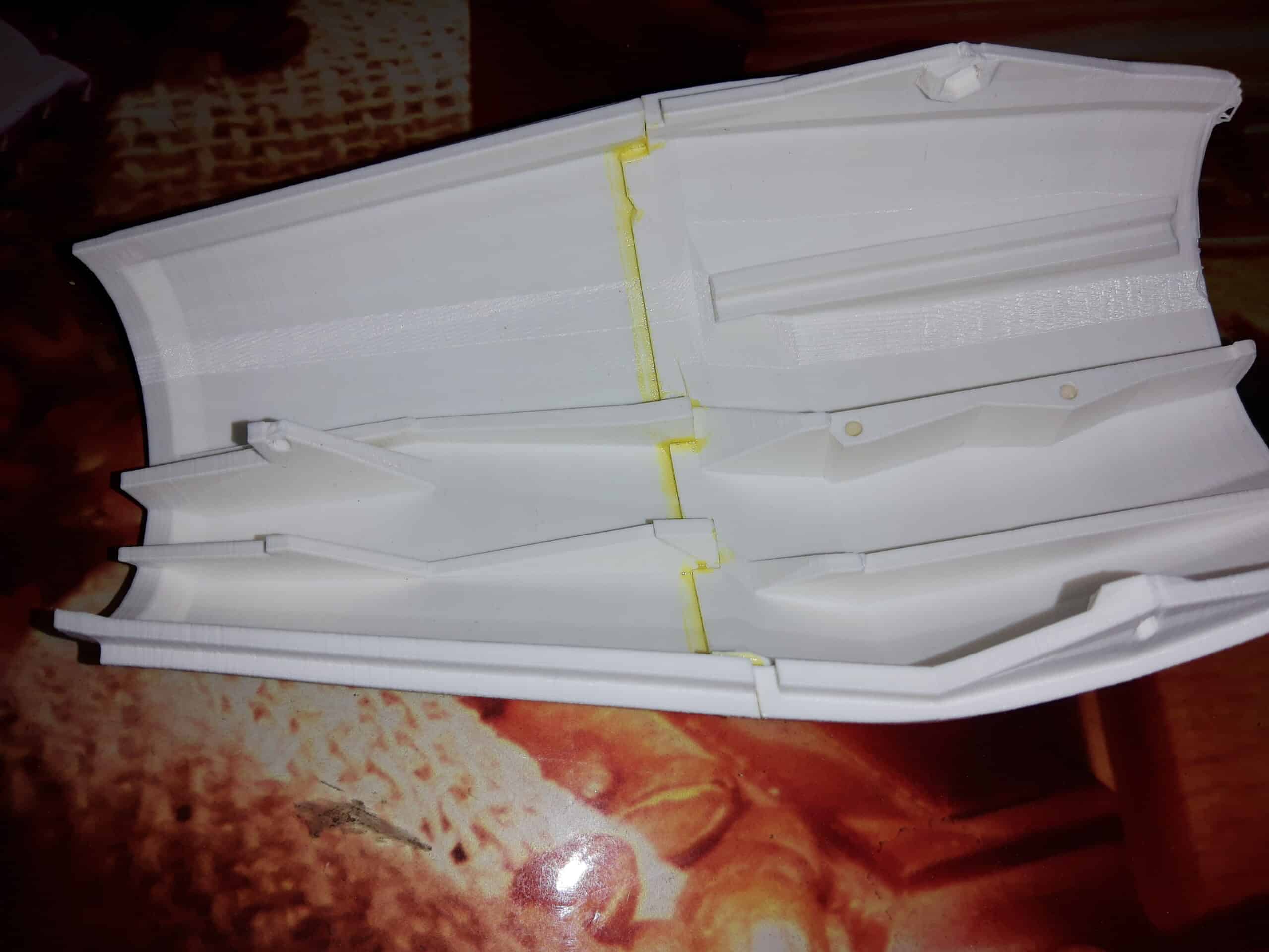
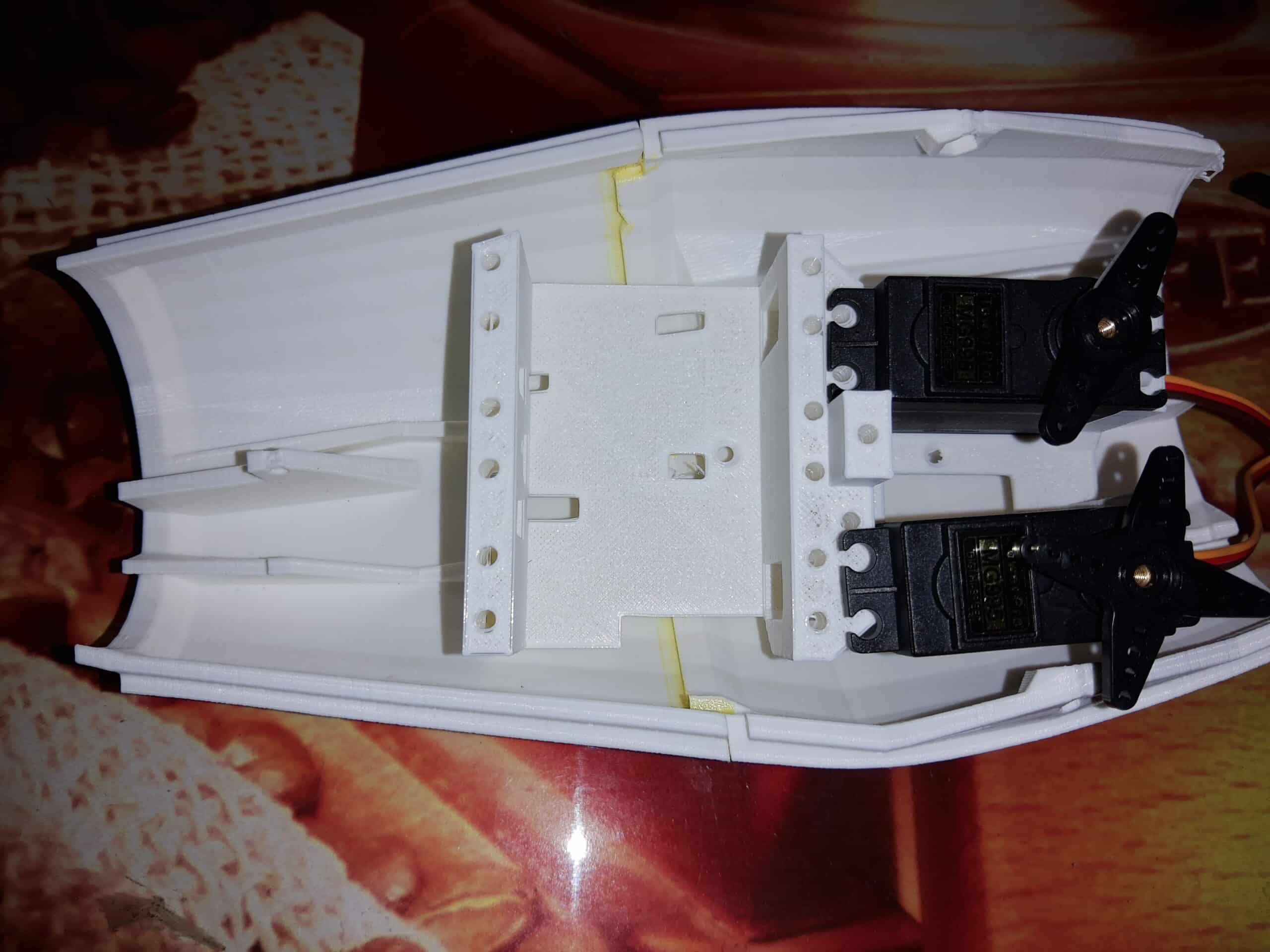
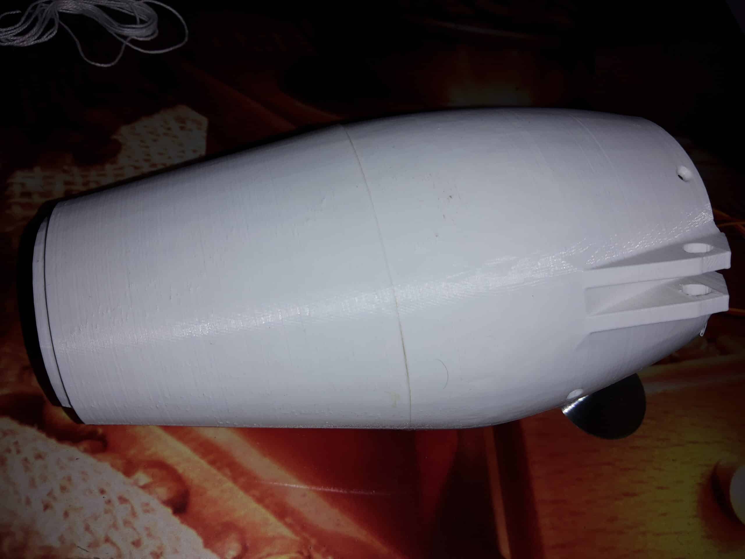
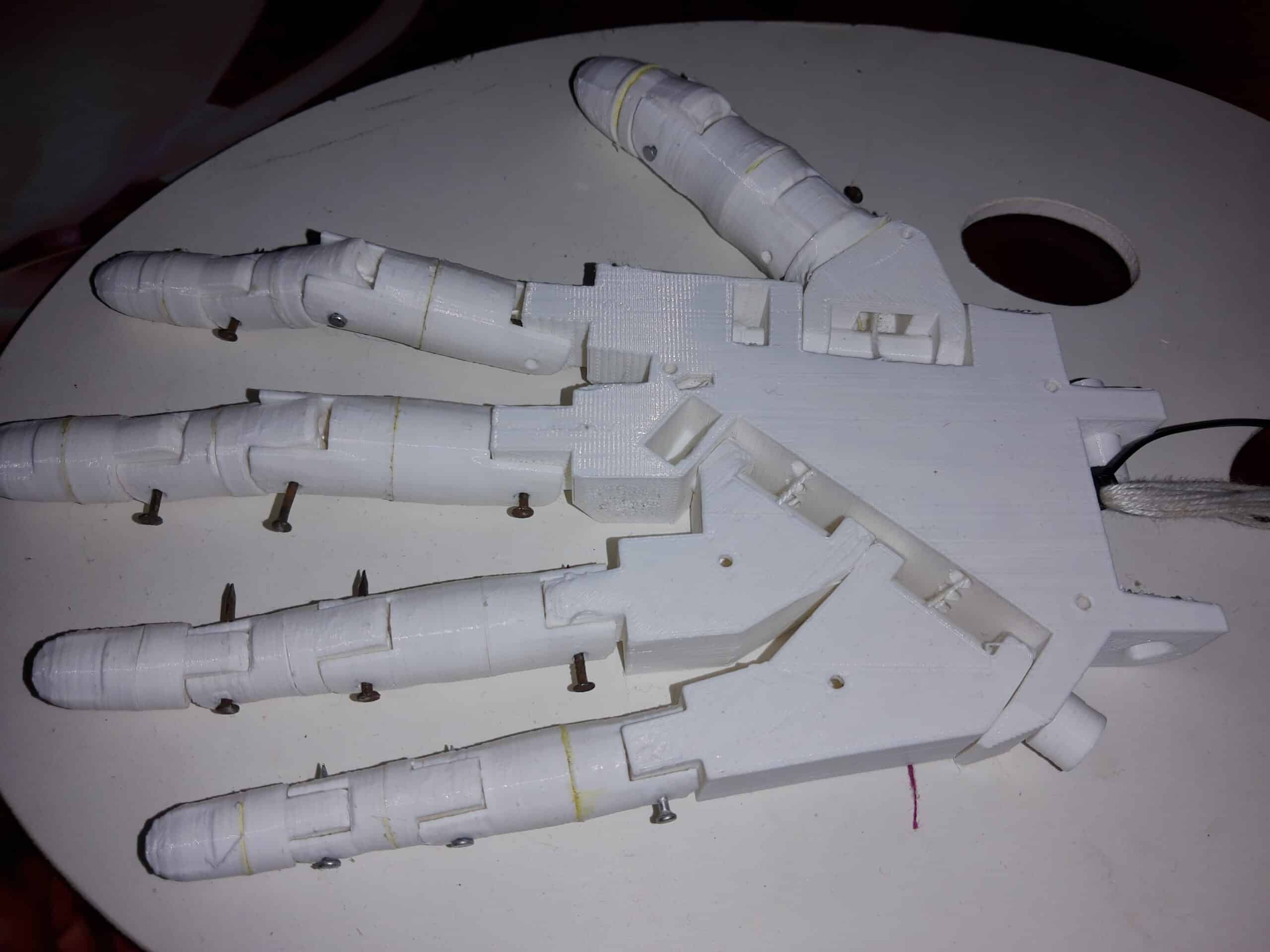
There are various open-source prosthetic body parts available in the market. You can also 3D print them at home. Here, I am using the InMoov robotic arm. After getting the required parts consisting of fingers and servo, assemble the prosthetic hand as shown in the pictures below.
Coding
Here we need to make two devices: a prosthetic hand data transmitter and a receiver with servo move mechanism. For each of them, we will create two separate codes.
Code for Transmitter
This is required for EMG data transmission to the prosthetic hand.
First of all, we need to define the pin numbers for the sensor and variables to store the EMG sensor data. Then create a setup function where the Baud Rate is set for Bluetooth and Serial Port Communication. The Arduino Pro Micro offers two hardware serial ports: one for USB and the other for RX and TX Pins. Use serial1 for Bluetooth communication by setting its Baud Rate to 9600 (which is the default for Bluetooth HC-05).
Then create a loop function for sending updated EMG sensor values to the Bluetooth at regular intervals of time.

Receiver and Prosthetic Arm Code
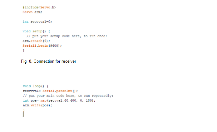
For the receiver, include the servo library servo.h in the code to control it. Then create a setup function to set the pin number for connecting the PWM signal wire of servo to control it.
Since Arduino Pro Micro has several PWM pins, we will use pin number 9 for servo PWM control. Next, start the serial to read the transmitter device value and then create a loop function to get the EMG sensor value over serial. Apply the EMG value to the servo degree rotation range, which is 0 degree to 180 degrees for servo and has values 60 to 800 for the EMG sensor.
Connection
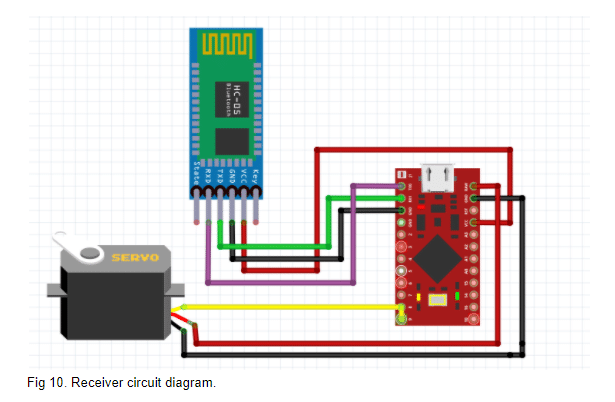
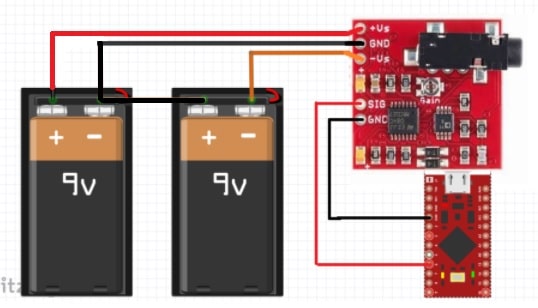
Connect the components for both transmitter and receiver as shown in the circuit diagram. For the EMG transmitter circuit, you need to add the Bluetooth module in the receiver circuit as well.
Note:- You need to configure both the Bluetooth modules for them to pair with each other and transmit/receive data accordingly. To do that, you can follow the instruction given in the project ‘wireless mouse’.
Next, write the mapped value to the servo move position to move the prosthetic hand finger as per signals generated from muscle movement.
Testing
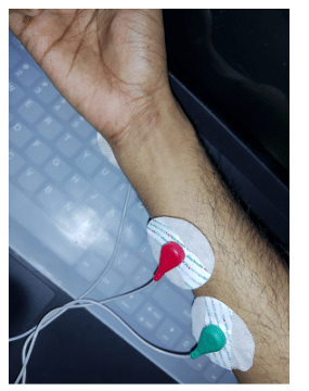
Now attach all fingers to the servo pulley for the prosthetic arm and power both the devices i.e. transmitter and receiver cum controller for a prosthetic arm. Then wear the electrodes as shown in Fig 12. The prosthetic arm will mimic the finger movements whenever you close and open your palm.
Congrats!! You have just developed an extra hand for you which can be controlled wirelessly.


Hey excellent project, I’ve decided to do this as my final year project. Can you please guide me to proceed with my project. Thankyou!
Kindly elaborate your query.
how is possible to transmit signal
Pls Kindly Reply
This is conform working or not
Here we take data from EMG sensor then transmit it using Bluetooth HC 05
That EMG sensor connection is correct
This circuit use two hc05
Two bluetooth module
Yes, both circuits have HC05 but in the EMG Circuit diagram, I have not shown Bluetooth HC 05 as it makes unreadable due to lots of wiring crossing each other the HC 05 Connection will be the same as circuit 1. Same thing I have stated in the article as well in connection section
How much did it cost(total) to 3D print every part ? Was the material used PLA or ABS for 3D printing.
Excellent project! The circuit diagram only shows connections to one servo motor, but the description of the project says it controls five servo motors. May you please elaborate on this? Your reply is appreciated. Thank you!
Amazing project! The circuit diagram only shows connections to one servo motor, but the description of the project says it controls five servo motors. May you please elaborate on this? Your reply is appreciated. Thank you!
Great project! I have one question. The circuit diagram only shows connection to one servo motor, but the project description states that it can control five servo motors. Is it possible to control five servo motors? If so, how? Your reply is greatly appreciated. Thank you.
yes, You can connect the 5 servo motor and connect the input to same pin of servo , you can also set new pin number to control the servo depending on the join you want to move
where in the receiver circuit would I connect the wires of the other four servos?