


 In process instrumentation and control, operators in the plant equipment control room monitor on-field sensors and send real-time commands to control actuators and final control elements such as motors, pumps, variable-speed drives, variable-frequency drives and electrically operated valves in the field using a human-machine interface (HMI) program for process control. A graphical user interface (GUI)-based HMI application enhances the user-friendliness of such an approach.
Signals from the operator station are usually sent to on-field actuators by using an industry-standard 4-20mA current loop protocol. However, due to inherent disadvantages during troubleshooting, control loop testing and plant commissioning stages of a wired communication based process plant, the trend in recent years has been towards operating plants wirelessly. For example, WirelessHART (Highway Addressable Remote Transducer) protocol based transmitters and actuators are widely used in modern process industries.
In this project, a GUI built on MATLAB environment is employed to wirelessly control four electrical equipment. Transmitter and receiver modules for this wireless equipment control operate at 434MHz frequency.

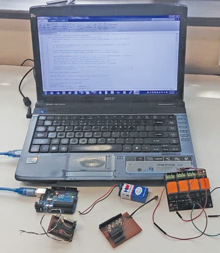
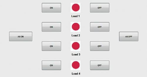
Authors’ prototype and the front panel of the MATLAB-based GUI are shown in Figs 1 and 2, respectively.
Circuit and working
Block diagrams of transmitter and receiver circuits are shown in Figs 3 and 4, respectively. The main components used in this project are described below.


Arduino Uno
Arduino Uno is an AVR ATmega328P microcontroller-based development board with six analogue input pins and 14 digital input/output (I/O) pins. The microcontroller has 32kB of ISP flash memory, 2kB RAM and 1kB EEPROM. The board provides serial communication capability via UART, SPI and I2C. The microcontroller can operate at a clock frequency of 16MHz.
In this project, digital I/O pins 8 through 12 of the Arduino are configured as output pins.
HT12E encoder
It is a 212 series CMOS LSI encoder for remote control applications. It is capable of encoding information, which consists of ‘N’ address bits and ’12-N’ data bits. Each address/data input can be set to one of the two logic states. Upon receipt of a trigger signal, the programmed addresses/data are transmitted together with header bits via an RF transmission medium. The capability to select a TE trigger on the HT12E further enhances the application flexibility of 212 series of encoders. HT12E IC has 8 address bits and 4 data bits.
HT12D decoder
This 212 series CMOS LSI decoder is widely used with HT12E encoder for remote control applications. It receives serial addresses and data transmitted from the programmed 212 series encoder. The decoder compares the serial input data three times continuously with its local addresses. If no error or unmatched code is found, input data codes are decoded and then transferred to the output pins.
The 212 series of decoders are capable of decoding the information comprising ‘N’ bits of address and ’12-N’ bits of data. The HT12D is arranged to provide 8 address bits and 4 data bits. For a valid transmission, address bits of both the encoder and the decoder must be the same.
SPDT relay
Relays used here are single-pole double-throw (SPDT) type. In this type of relay, the output side has three terminals: normally open (N/O), normally closed (N/C) and common (C). When the relay is not energised, N/C and C terminals are short-circuited, and N/O and C terminals open-circuited. When the relay coil is energised, N/C and C terminals are open-circuited, and N/O and C terminals short-circuited.
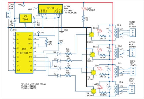
Circuit diagrams of transmitter and receiver units are shown in Figs 5 and 6, respectively.
When a pushbutton is pressed in the GUI, the code executes a callback function in MATLAB. Commands to set or reset digital I/O pins 9 through 12 of the Arduino are written within that ‘callback’ function. After a pin is set or reset, the encoder scans the status of digital pins and transmits it wirelessly to the receiver side using the 434MHz wireless transmitter.
The transmitted data is received by the receiver and decoded to energise or de-energise the relays accordingly. When a particular digital I/O pin is set high by pressing the pushbutton, the corresponding relay energises. Four BC547 BJTs (T1 through T4) are additionally used, as IC3 cannot directly source sufficient current to energise relays.
Diodes D1 through D4 are used as protection diodes to prevent sinking of current into IC3. Diodes D5 through D8 are fly-back diodes, which prevent damage to electronic components due to the back emf produced by the inductive action of the relay’s coil. LED1 indicates power-on status of the circuit, whereas LED2 through LED5 show the status of the four relays. The power to the relay board is provided separately from a +9V battery.
Software program
We have used Arduino IDE for programming the Arduino Uno. The latest IDE can be downloaded for free from Arduino’s official website. After downloading the Arduino IDE, install it. Note the directory of the Arduino IDE installation. Follow the steps given below for this project:
1. Download the ‘Legacy MATLAB and Simulink Support for Arduino’ package from Mathworks website. Extract the compressed folder named ‘ArduinoIO’. From ArduinoIO folder, copy folder ‘pde’ and paste it in C:\Program Files (or Program files x86)\Arduino\libraries. (The path may be different depending on the installation directory of the IDE.) After pasting the pde folder in the correct location, open Arduino IDE. If you have pasted the folder in the correct location, you can find ‘pde’ by clicking File Examples pde. Open the code by proceeding as follows: File Examples pde adioes.
2. Connect the Arduino Uno board to your PC. From Device Manager, note the COM port at which the Arduino Uno board is installed. From Tools menu in the Arduino IDE, select the board as Arduino Uno, followed by the COM Port number noted earlier. Upload ‘adioes’ code to the Arduino Uno board by pressing ‘Upload’ button in the IDE.
3. Now copy the entire contents of the extracted ArduinoIO folder to a folder in ‘My Documents’ (for Windows PC).
4. This GUI application program is developed in the R2014a version of MATLAB. After installing this version of MATLAB in your PC, open the file ‘install_arduino.m’ from the directory where you have copied the contents of ArduinoIO folder. Now run the install_arduino.m file. The code will correctly install and save the path of the Arduino support package.
5. Open the project’s source code file titled ‘relay_control_wireless.m’. Edit the line a=arduino (‘COM9’) with the COM port number in your PC where the Arduino Uno board has been installed. When you run the project file, MATLAB will try to communicate with the board. After successful communication is established, you can control the equipment by pressing the appropriate pushbutton in the GUI.
Download source folder
Construction and testing
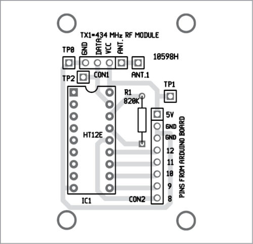
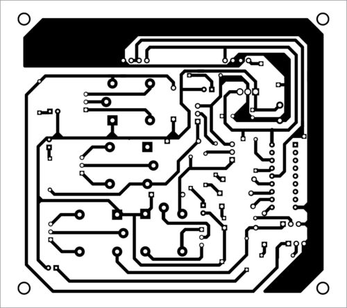
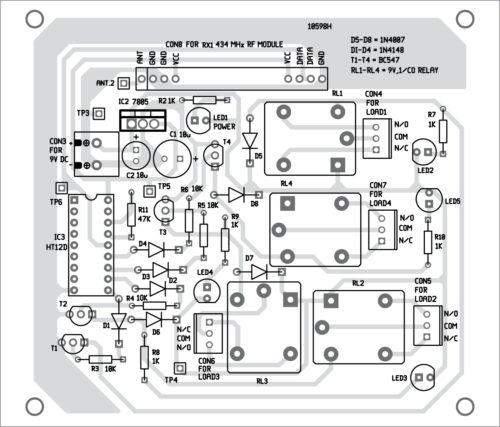
A PCB layout of the transmitter side is shown in Fig. 7 and its components layout in Fig. 8. Similarly, actual-size PCB layout of the receiver is shown in Fig. 9 and its components layout in Fig. 10.
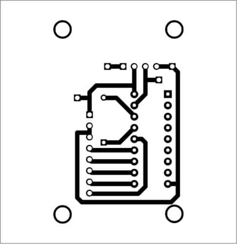
Download PCB and component layout PDFs: click here
Connect the transmitter unit of Wireless equipment control to the PC. After uploading the Arduino code into Board1 as explained above, run the MATLAB GUI program. Next, connect 9V battery to the receiver unit. Keep transmitter and receiver unit one meter apart. From the GUI program, click ‘on’ or ‘off’ button to switch on/off the corresponding electrical device. The ‘on’ status of the devices is indicated by the glowing of LED2 through LED5.
For troubleshooting, the expected values/voltages at various test points are listed in the table above.
Read our other MATLAB Based GUI Projects


How will we control the status of devices?