 Here is a low-cost and simple wireless stepper motor controller using infrared signals. Using this circuit you can control the stepper motor from a distance of up to four metres.
The circuit comprises transmitter and receiver sections. The communication between the transmitter and receiver sections is achieved through infrared signals.
Wireless Stepper Motor Controller Circuit
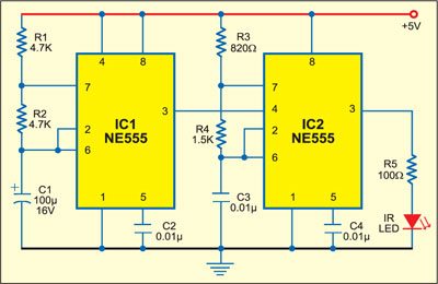
In the transmitter section, timer NE555 ICs (IC1 and IC2) are configured as astable multivibrators with frequencies of around 1 Hz and 38 kHz, respectively. The output of IC1 is given to reset pin 4 of IC2, so the 38kHz carrier signal is modulated by 1Hz modulating signal. The modulated signal from pin 3 of IC2 is transmitted by the infrared LED. Resistor R5 limits the current through the IR LED.

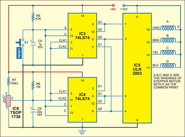
The transmitted signal is sensed by IR receiver module TSOP1738 (IC6) of the receiver section and its output at pin 3 is used as clocks for dual flip-flop 74LS74 Ics (IC3 and IC4), which are configured as a ring counter.

When the power is switched on, the first flip-flop is set and its Q1 output goes high, while the other three flip-flops are reset and their outputs go low. On receiving the first clock pulse, the high output of the first flip-flop gets shifted to the second flip-flop. Thus on reception of every clock pulse, the high output keeps shifting in a ring fashion.
The outputs of flip-flops are amplified by the Darlington transistor array inside ULN2003 (IC5) and connected to the stepper motor windings marked ‘A’ through ‘D.’ The common point of the windings is connected to +12V DC supply.
To stop the motor, the flip-flops can be reset manually by pressing reset switch S1. On releasing the reset switch, the stepper motor again starts moving. If any interruption occurs between the transmitter and the receiver, the motor stops.
For more exciting circuit articles: click here
The article was first published in March 2005 and has recently been updated.


plz provide pcb layout of this circuit
can we change the no of steps per one rotation?if yes can u explain us?
plz provide pcb layout of this circuit.