


 VU meter is a standard device that indicates the signal level in audio equipment. Unlike other devices, this meter doesn’t require a physical connection between the audio source and the circuit.
Wireless VU meter circuit
Circuit diagram of the wireless VU meter is shown below. It is built around an ATmega32A IC (IC1), a bar graph LED (BAR1), a 1N4148 diode (D1), transistors BC547 (T1) and BD139 (T2), and a few other components.
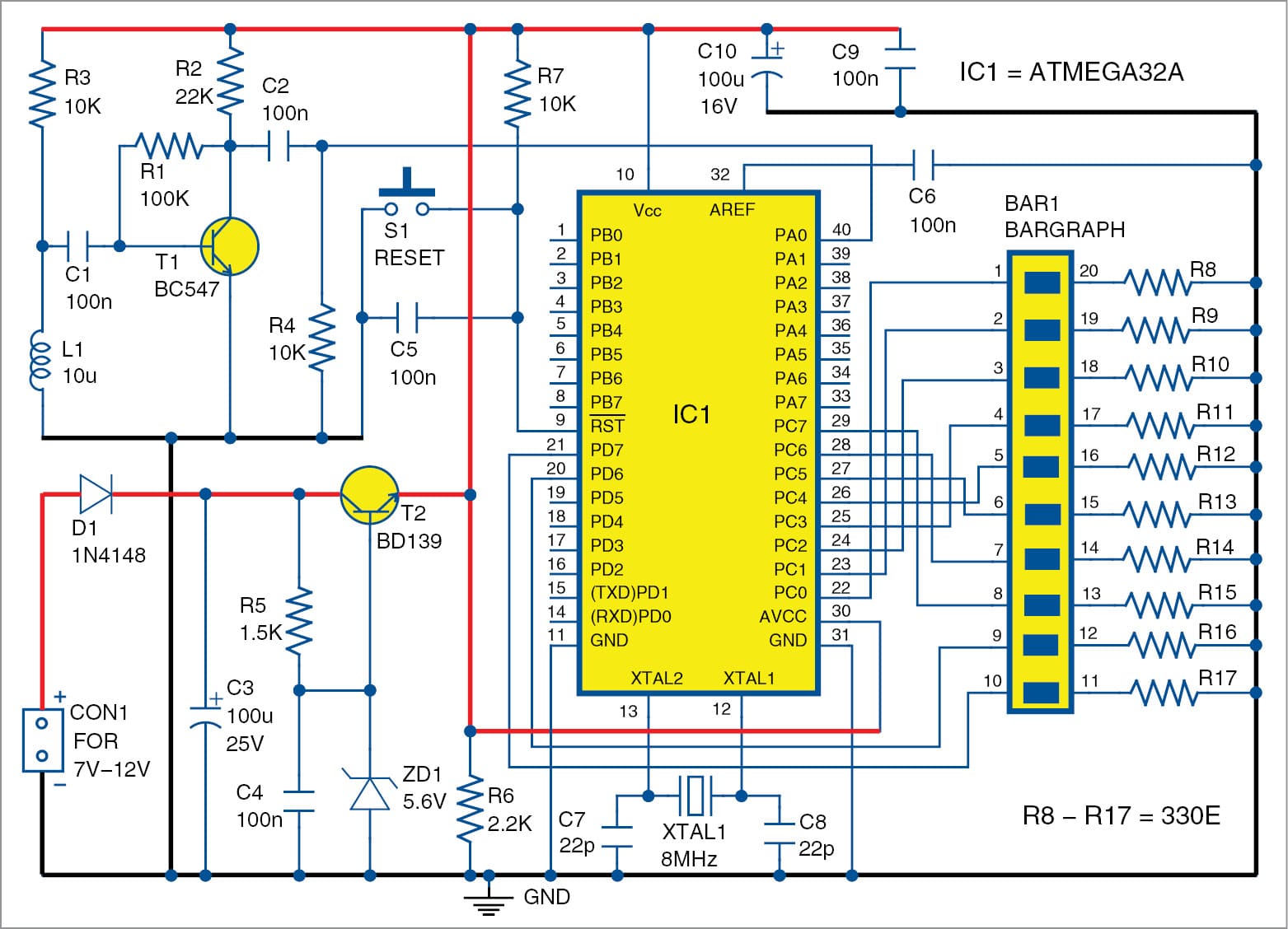
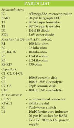

Transistor T2, diode D1, Zener diode ZD1 and passive components form the linear voltage regulator. A 7V-12V, 200mA power source is connected to connector CON1. Diode D1 is used to protect the regulator from reverse voltage connection and capacitor C3 reduces the noise in the power supply lines. Resistor R5 sets the Zener diode (ZD1) current. The output voltage at the emitter of T2 is around 4.9V.
A preamplifier or small-signal amplifier is built around transistor T1, where resistor R2 sets the collector current, R1 is the feedback resistor to set the proper gain, and capacitors C1 and C2 are the input and output coupling capacitors, respectively.
Circuit operation
The speaker of any audio device produces magnetic fields according to the music. These magnetic fields are sensed by inductor L1 (10µH) and amplified by the preamplifier circuit built around T1. The output of the preamp circuit is fed to the analogue-to-digital converter (ADC) pin 40 of the AVR microcontroller (IC1). The output voltage of the preamp circuit is below 2Vpp and the ADC reference voltage is 2.5V.
The microcontroller processes the input signal to drive the bar graph LED (BAR1) connected to Port C of IC1. The louder the music signal, the more the number of LEDs that glow in the bar graph.
Software
The code is written in C language and compiled using Atmel Studio 6.2. The hex code (VUmeter.hex) is uploaded to the microcontroller using an STK500 programmer. At EFY Lab, ProgISP programmer was used to burn the hex code with the following fuse-bit settings:
HIGH = 0xD9
LOW = 0xFF
Do not forget to set these fuse bits before uploading the source code.
Download source code
Download PCB and component layout PDFs: click here
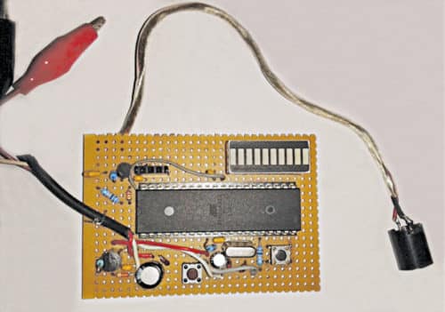
Construction and testing
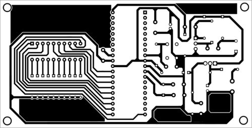
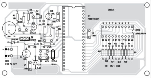
Assemble the circuit on a PCB. Put the PCB in a suitable enclosure and place inductor L1 near the audio device’s speaker. After uploading the source code and inserting the MCU into the PCB, connect the 7V-12V regulated power supply to CON1. The last two LEDs of the bar graph LED are connected to pins 20 and 21 of IC1 to indicate the presence of power in the circuit. PCB and components layout of the wireless VU meter is shown below.
Sir I am studying m.sc final year physics.iam interested in electronics pls suggest me any electronics projects which was not program based