


 A wired water-level indicator uses many wires, whose resistance increases as their length increases. A wireless water level indicator using microcontroller (MCU) is costly and not very easy to program. Presented here is a low-cost wireless water level indicator without an MCU.
This circuit has transmitter and receiver units. The transmitter unit is placed near the water tank, whereas the receiver unit is placed inside the house for monitoring four different levels: low, middle, full and overflow.
Wireless water level indicator circuit
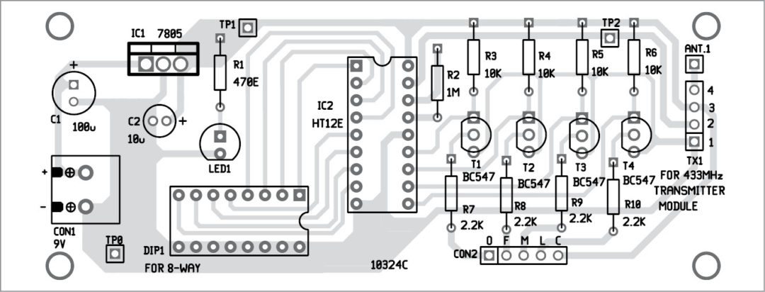
Circuit diagram of the transmitter unit is shown in Fig. 1. It consists of 433MHz RFtransmitter module TX1, an encoder HT12E (IC2), a 5V regulator 7805 (IC1), DIP switch DIP1, npn transistors BC547 (T1-T4), connector CON2 for connecting the sensors in the overhead tank and a few other components.
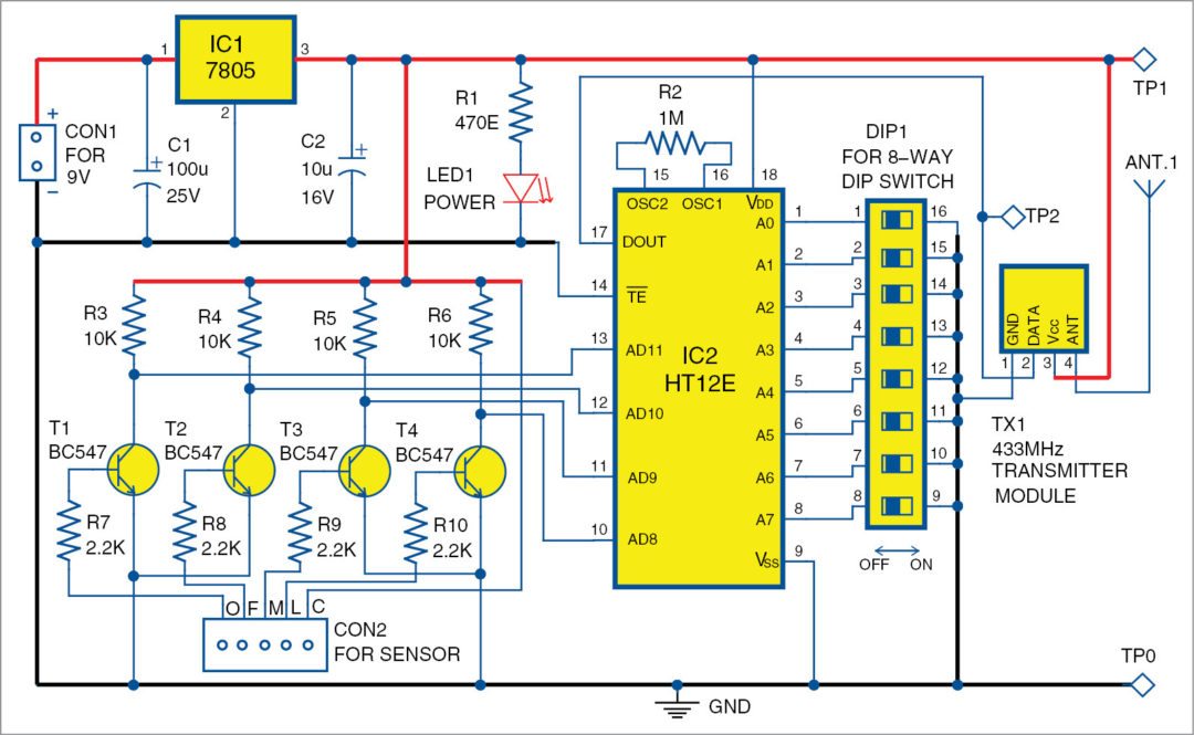
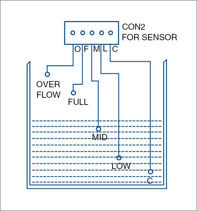
Bases of T1 through T4 are connected with resistors R7 through 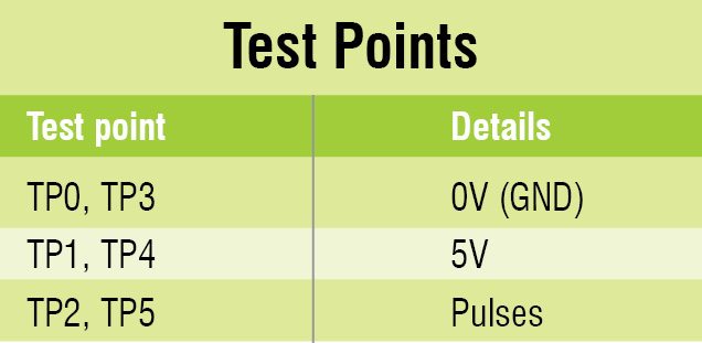 R10. Each water-level sensor is connected to the circuit through R7 through R10. Water levels are marked as low (L), middle (M), full (F) and overflow (O) in the circuit. The common terminal is marked as C on CON2.
When  water level increases, the transistors conduct and the output signal at their collector changes. Output of each transistor is fed to IC2. Encoded data from IC2 is transmitted through TX1.

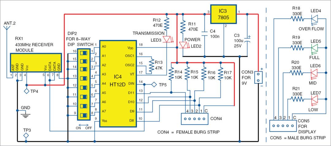
Circuit diagram of the receiver unit is shown in Fig. 2. It consists of 433MHz RF receiver module RX1, a decoder HT12D (IC4), 5V regulator 7805 (IC3), DIP2 switch, LEDs (LED4 through LED7) and a few other components.
Data is received by RX1 and decoded by IC4. Different water levels are indicated by the glowing of LED4 through LED7. Resistors R14 through R17 are pullups connected to IC4.
General-purpose 9V batteries are used to power both the circuits. LED1 and LED2 are power indicators and LED3 is used to indicate a valid transmission status.
Construction and testing
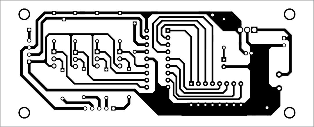
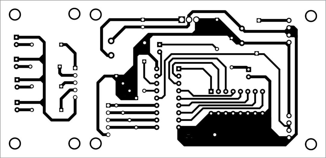
An actual-size, single-side PCB for the transmitter unit is shown in Fig. 3 and its component layout in Fig. 4. An actual-size, single-side PCB for the receiver unit is shown in Fig. 5 and its component layout in Fig. 6. After assembling the circuits on their PCBs, enclose these in separate plastic boxes.
You can use 9V regulated power supplies instead of batteries to power the circuits. For troubleshooting, check voltages at various points mentioned in the test point table.
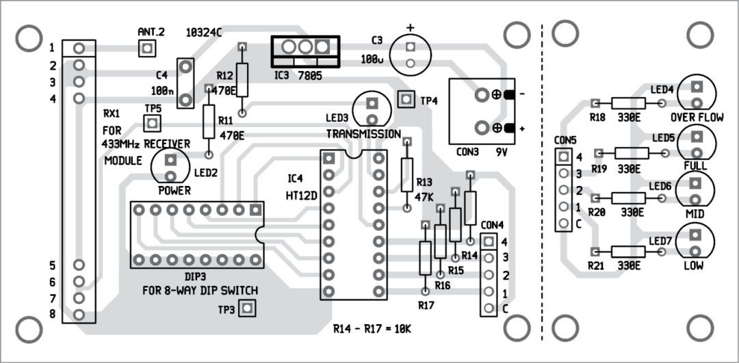
Make a separate PCB for the LED indication (shown by the dotted lines on the right side of Fig. 6). Use different LED colours for different levels.
Use a waterproof box for the transmitter unit to protect it from rain water.
When both the circuits are switched on and LED3 glows, it indicates that the transmitter unit and the receiver unit are connected successfully. If the addresses of the units are different, LED3 will not glow.
Use DIP switches (DIP1 and DIP2) to set the addresses. Switch on pins 1, 2 and 7 of both the DIP switches to make a secure connection.
This will prevent interference from nearby RF transmitters. Connect the sensors in the tank as shown in fig .7.
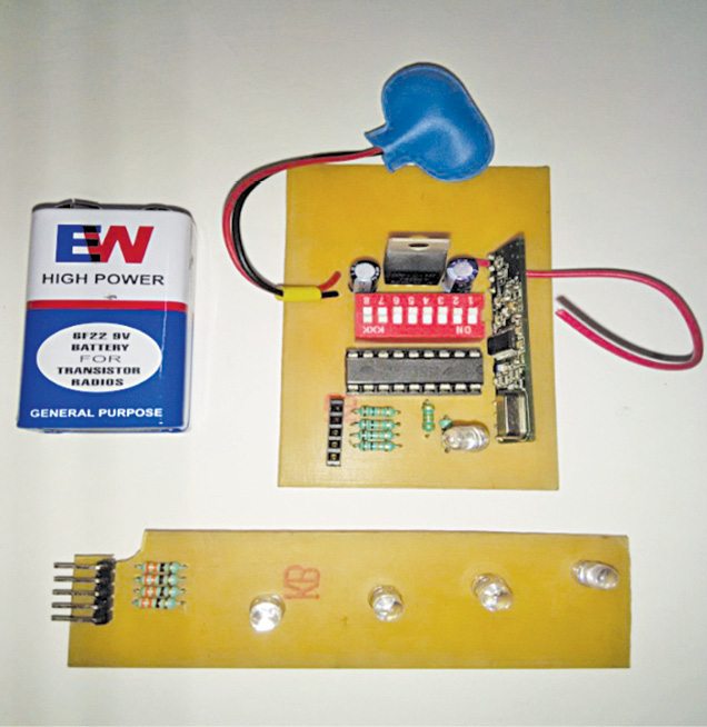
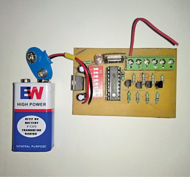
Author’s prototypes of the transmitter and receiver units are shown in Figs 8 and 9, respectively.
Download PCB and Component Layout PDFs: click here
Pranav Rameshji Rokde is a Electronics enthusiast from Nagpur, Maharashtra


pl suggest / recommend a low cost water level sensor. the metallic contact type arrangement fails. what is the life of normal 9V battery in the above circuit
Hello sir,
You can use float sensor which is easily available in near by electronics market.
Normal 9V battery life is near about one to two week but you can use rechargeable batteries .
hello sir,
you can soldered at metallic contact which can increased that contact life or you can use float sensors which easily available near by electronics market at low cost.you can also refer datasheet of float sensors.
You not mention anything about sender send all the time and battery will soon be die !
– and I missing info why HT12E encoder osc. is 1 mohm while HT12D decoder osc. is 47Kohm !? – don’t they need to be same ?
Regards Erik
Hellow sir, While designing and testing these values are sutiable…and you can also use rechargable batteries insted of regular batteries
Hellow sir, While designing and testing these values are sutiable…and you can also use rechargable batteries insted of regular batteries
what happens if my neighbour also uses this project. will the rf interference occurs.? if so what is the solution?
You can change the dip switch sequence for each instillation so different sequence for all. Both the sequence need to match up at receiver and transmitter side.
Hello sir, yes RF interference occurred but by changeing dip switch code your wireless water level indicator dose not interference with your neighbors…..
i triple checked my circuit and replace decoder ic twice.At my receiver unit all led are glow continuously,either transmitter unit is ON or OFF transmission LED always HIGH, and i checked the test points and all voltages are as mentioned…..plz…plz help me…..thanks in advance for your help..
Sir, kindly check your transmitter section, there may be linked problem or also their may be problem with your RF Modules..
hi sir ,we can made choise your project than plz give me a contact no there are many information has been help ….my mail [email protected]
Kindly elaborate your query.
Purchase
Kindly elaborate your query.
What shall we use for the sensors? And is it supposed to be directly connected to the CON2?
Yes you can directly connect sensors to CON2. Stainless steel rods for use as water level sensors are available in the market.
what is the maximum distance range between transmitter and receiver?
The range depends on the type of RF modules and the antenna used. You can easily get RF modules ranging from 30 meters to 90 meters.
i have done the connections stated, but my LED 3 is not glowing. please help
Sir give me proper working of this project detail information I am ready to circuit but out put not geting sir plz help me my last sem project and few days avliable my mail id – Chaskarjitendra95@gmail
Please go through the text again especially Circuit and working section. Make sure that the address lines A0-A7 of HT12E and HT12D should be same.
friend i need to make the project
i need full component of the project can you sent the component to the UAE with full drawing and should be pirnted circuit board with mension
can you give full spare parts to me to UAE
@ Peer Mohamed : This particular project isn’t available with us. To view entire range of DIY projects kits, development boards etc, visit kitsNspares.com
on what software the wireless water level control will compile
please sir help me it was given as final project
thank you.
Please elaborate your queries
Sir how set the dip switch .Can we make it without dip switch
Yes, but without DIP switch you won’t change address line according to you and it is difficult to connect wires in this PCB layout in place of DIP switch. If you leave all the address line pin floating then it is chance for decoder IC may receive garbage value.
Sir if I paid Can u give all components
and you can get all the component on ebay.in or http://www.electroncomponents.com.
Hi,
Please go through the below link and see if it fullfill your need.
https://kitsnspares.com/user2/led_product_description.asp?id=106
Hi EFY,
The great things are always beautiful ,such as the diy projects of EFY.
here I am thanking you in advance for the better job.
can I add a relay circuit with this to control the single phase 1hp motor?
if so please sent me the circuit with description through my email.
Hi Abdul,
Thanks for the feedback! Yes, you can add relay circuit but with a slight tweak in the circuit to turn on/off the motor.
Sir how we can add relay switch to turn on/off motor…what is the changing in this circuit..in detail..
hello sir,
i am all ready water lavel
how to convert wirless
Sir if we not connected dip switch then any problems occurred?
hi every one,
i am an engineering final year student, as apart my final project i am looking for a water level sensing element which must have wireless technique. i had the complete signal conditioning and processing circuit, but i need a sensor to detect water level(NON CONTACT TO WATER). Actually, i tried a lot around the internet but i didn’t succeed. could any one help me.
Try magnetic float and reed switch sensor and connect to transmitter of wireless water level indicator
Plz mention maximum working distance between transmitter and receiver .
For this project from where did you purchase the rf module and what was the price thank you.
Hello EFY, your project are too good….i want to add in this wireless water level indicator for overflow led replace by buzzer. So,can i connect buzzer in place of led 4. I tried to register on your website but the password is not coming on my mail. Please help me about this….
in place of 9 v connector cna i make a small ckt of bridge to produce 5v.
Can i use 12v battery
and
with
change the
IC 7805 to 7809
?????????????????
Sir, what would be the size of pcb layout..
hi,
i want to know complete details about TX1(433 MHz transmitter module) and RX1(433MHz receiver Module) datasheets and where i can purchase these two
Hi,
How to switch on the Motor at low level of the overhead Tank when the contact pins opened with HT 12 E, it can be done with float switch but I would like to use contact sensor.
better if you could introduce with Automatic water pump section also.
[email protected],
if you can pls send me Arduino Uno code for the following requirements
I want use Auto and Manual Button. and to be displayed an LED Auto or Manual
and I want to Display two LED’s “Pump Running” or “Standby”
I want use Pause/Standby button when pressing this button Led must be glow “paused” and the button press again Pause led must be off and Standby LED must be glow.
pls help
Nilantha.
Hi Sir Good Afternoon i am trying to interface the water level sensor using Arduino nano for harvesting the fish Aquarium automatic water level detecting and filling the water below average of water but, the tank depth was 45CM the sensor size only the 5 cm how to apply the same application using long height sensor OR if any chance to increase the size of sensor please reply this question sir thank you
Hi Sir Good Afternoon i am trying to interface the water level sensor using Arduino nano for harvesting the fish Aquarium automatic water level detecting and filling the water below average of water but, the tank depth was 45CM the sensor size only the 5 cm how to apply the same application using long height sensor OR if any chance to increase the size of sensor please reply this question sir thank you
This is by far the worst design based on cost, design, and circuit board layout. You will have issues with interference. Total waste of a chip at that price. Power supply is a horrible design.
Thanks for the feedback! Different designers have different ways of making things. Please elaborate each problem so that our readers can also benefit from your comments. This circuit was working well during the time of testing. Again the circuit uses inexpensive and easily available components. If you have some better ideas, please send your circuits to us, we would loved to publish them if found suitable for our readers.