


FEBRUARY 2012: The robotics team of M.S. Ramaiah Institute of Technology has developed an autonomous unmanned ground vehicle (UGV) named Moksha. The objective of the project was to build an autonomous ground vehicle capable of following a prescribed track while avoiding obstacles in its path, to reach specified geometric locations.
The Moksha-UGV team was divided into five groups based on the different requirements of the project, namely, computer vision, light detection and ranging (LIDAR), GPS, motor controller and power systems.
Innovative approach to hardware

Project Moksha-UGV included various innovations:
Split-frame chassis. The chassis of the UGV is designed using split-frame technology. The chassis is split into two frames—a rear frame and a front frame. The two frames are interlinked via the flexible joint supported by a suspension system.
This split-frame design helps the robot easily manoeuvre through difficult terrains. The suspension system helps keep the UGV stable. Thus the UGV can easily cross ramps and rugged terrains.
[stextbox id=”info” caption=”Hardware Specifications”]Material used Mild steel
Length 116.8 cm (3 feet 10 inches)
Width 73.7 cm (2 feet 5 inches)
Height 96.5 cm (3 feet 2 inches)
Wheels Four
Motors Two (each 24V DC, 1.8A max, 120W)[/stextbox]
Camera angle. As a convention, front-facing cameras are used in vehicles to capture a complete scenario. In the UGV’s implementation of image processing, only one camera is used, which is inclined downwards to amplify the details captured by the camera. This also prevents the unnecessary details that creep in when a conventional position is used. By making these small changes, a major overhead of filtering out the details is avoided.
Fabrication. The body of the UGV is fabricated using polyurethane material, which is very light and sturdy. Several compartments are made to keep the various components being used in the UGV so that the components remain in place even when the vehicle moves. The body provides protection to the components and also acts as an insulator.
The height of the camera’s arms is varied with a simple slot-and-screw mechanism. To optimise the use of space, the battery unit is kept below the vehicle in a drawer.
Solar energy. Power system includes a compact battery and solar panels. Solar panels provide energy to the vehicle even if the battery fails. These also ensure that the size of the batteries is reduced and introduce the use of green technology.
Power supply board. The power supply board is made from wood and the terminals are mounted. The board helps in power division and also provides sturdy connections. Power is provided to all parts of the vehicle from the power supply board. The power system is designed taking the real-time scenario under consideration in such a way that it provides power to the system without any fluctuation.
Circuit description
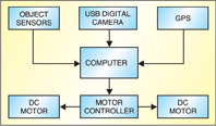
The hardware of the UGV is divided into three sub-units—drive train, control and perception. The UGV is a four-wheeled, two-DC-motored differentially-driven vehicle.
The control unit consists of RS160D motor controller. The motor controller is connected to a laptop, which serially communicates with the controller to control the vehicle’s motion. The computer also receives and processes data from the perception unit which comprises three sensors, namely, ROD 4-20 LIDAR, MaxSonar and Garmin 18HVS GPS device.
Perception unit. The three sensors help Moksha perceive its surroundings as follows:
ROD 4-20. It is an optical distance-cum-angle sensor, which uses infrared and laser light sources to detect objects, sweeps at 180 degrees and returns distance and angle at a rate of 25 scans per second (range adjustable).
MaxSonar. It is an ultrasonic range-finder sensor that can detect objects within the range of 0-6.5 metres. It needs only 5V power supply and gives an analogue output, which is easier to process.
Garmin GPS 18 OEM. It is WAAS-enabled and available in CMOS-level serial or USB 2.0 full-speed versions. It comes with an integrated magnetic base, which is sufficient to provide an extremely high level of accuracy.
Motor control. The UGV employs Robot-Solutions’ RS160D motor control. RS160D servo uses custom software to implement a 2.5-channel high-powered servo system. The servo uses a quadrature encoder feedback mechanism to control torque, velocity and position of the output. It operates in pulse-width-modulation (PWM) mode communicating serially with the processor through an RS232 cable.
Data is sent in ASCII format from the processor using Visual C++ platform. RS160D is a two-channel controller. Each channel controls two different motors (right and left).
Data is sent as:
“@0sm1” selects mode 1, i.e., PWM mode,
“@0sj0” selects serial communication mode
“@0st255” selects torque control
