Read Part 3
Operational basics, salient features and military specific applications of ring laser gyroscopes and fibre-optic gyroscopes are discussed in this part of the article.
Gyroscopic sensors constitute an essential component of inertial navigation sensors (INSes), which are extensively used on a range of aerospace vehicles. These include commercial airliners, military aircraft and spacecraft.

Another military application of optronic gyroscopic sensors is their use for mid-course correction of guided missiles. In the case of inertial navigation guidance, the vehicles use onboard sensors to determine their motion and acceleration with the help of gyroscopes and accelerometers. A gyroscope is used to measure angular rotation, whereas an accelerometer is used to measure linear motion. The two are combined into a single unit along with a control mechanism, and the unit is called inertial measurement unit (IMU), or INS.
Two very important laser-based gyroscopic sensors include ring laser gyroscope (RLG) and fibre-optic gyroscope (FOG). Operational basics, salient features and military-specific applications of the two types of optronic gyroscopic sensors are discussed in this part.
Ring laser gyroscope
Ring laser gyroscope, or RLG, is an important optronic rate sensor and, in essence, the heart of any INS. There are different types of gyroscopic sensors such as spinning wheel mechanical, dynamically-tuned, ring laser and fibre-optic.
RLG offers superior performance as compared to conventional spinning-type mechanical gyroscope. RLG has no moving parts and therefore no inherent drift terms due to absence of friction. Unlike a mechanical gyroscope, RLG does not resist changes to its orientation. A combination of three orthogonally-placed RLGs makes a rate sensor with three degrees of freedom.
RLG is primarily a rate sensor. It can be used to measure rotation by integrating rate information. It essentially consists of two counter-propagating laser beams over the same path. It operates on the principle of Sagnac effect, according to which null points of the internal standing-wave pattern produced by the counter-propagating laser modes shift in response to angular rotation. Shift in the nulls of the standing-wave pattern manifests itself in the form of a moving interference pattern observed by combining two laser modes.
The basic concept of RLG can be explained as follows. Frequency of oscillation in a linear laser is such that the laser cavity consists of an integral number of wavelengths. Linear laser cavity is constituted by double pass of the distance between two mirrors. Since it is imperative that the beam replicates itself for successive passes over the cavity length, there will always be nodes at the two mirrors, and the two oppositely-propagating laser beams comprise a standing wave.
In the case of a ring laser, two oppositely-directed laser beams can be considered as travelling waves, and there is no such constraint of having a node at the mirror. The two beams in this case can be independent of each other and oscillate at different amplitude and frequency. Oscillation frequency of each is determined by the optical path length and not the geometrical path length. Thus, any mechanism, rotation in this case, which produces an optical path difference, results in different frequencies of oscillation for the two laser beams.
If the rotation is in clockwise direction, the clockwise laser beam sees a larger optical path length than the path length encountered by the counter-clockwise beam. For rotation in counter-clockwise direction, it is the opposite. Frequency difference is proportional to the rotation rate of the cavity.
Thus, by measuring frequency difference, rotation rate of the cavity and the platform it is strapped on to can be measured. According to Sagnac equation, frequency difference is given by:
∆ν = 4AΩ /lP=KΩ
where A=encircled oriented surface area of the ring laser, P=perimeter,λ=wavelength and Ω=rotation rate. The parameter (K) is called scale factor, which is measured in Hz/radians/s.
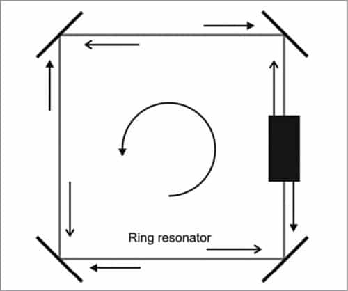
Fig. 1 shows square ring laser geometry, which is one form of geometry in use. In the case of square ring laser geometry, four mirrors form a closed light path. A small part of the ring laser path houses the excited gain medium. Gain medium along with mirrors are responsible for producing two counter- propagating laser beams.
Frequency difference produced as a result of rotation is obtained by the interference of the two beams. The two beams are usually combined with the help of a corner prism, as shown in Fig. 1.
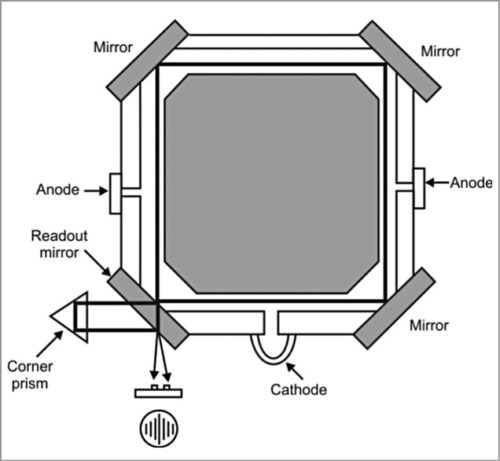
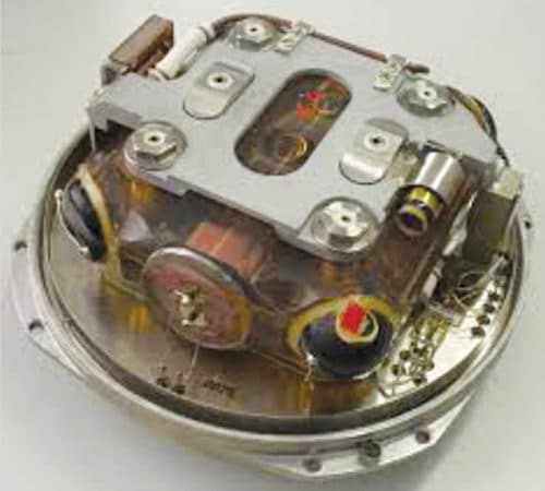
Figs 2 and 3 bring out the constructional features of the square-type ring laser geometry.
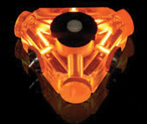
Another commonly used ring laser cavity structure is triangular geometry, as shown in Fig. 4. This type of geometry is popular with RLGs from Honeywell. Fig. 5 shows a lasing triangular ring laser cavity.
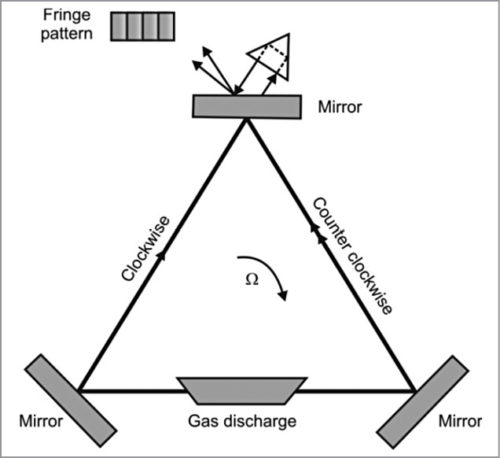
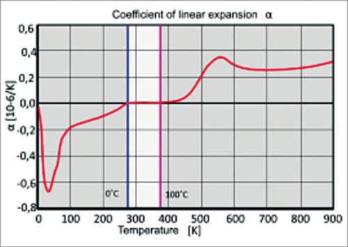
Going back to Sagnac equation, constancy of A and P is important to achieve the kind of angular resolution present-day RLGs are capable of. It is due to this that the gyroscope cavity material should have near-zero thermal expansion coefficient.
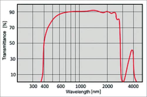
ZERODUR is one such material. It is a registered trade name of a near-zero thermal expansion transparent glass ceramic made by Schott, Germany. The material has a near-zero thermal expansion coefficient over a temperature range of 0°C to 100°C (Fig. 6) and transmission of 90 per cent in the spectral range that extends from 400nm to greater than 2000nm (Fig. 7).
RLGs suffer from lock-in effect at very low rotation rates. When the rotation rate is very low, frequencies of counter-propagating laser beams become almost identical. This leads to the two beams getting injection-locked to a common frequency. As a result, it does not respond to rotation. This is illustrated in the transfer characteristics of Fig. 8.
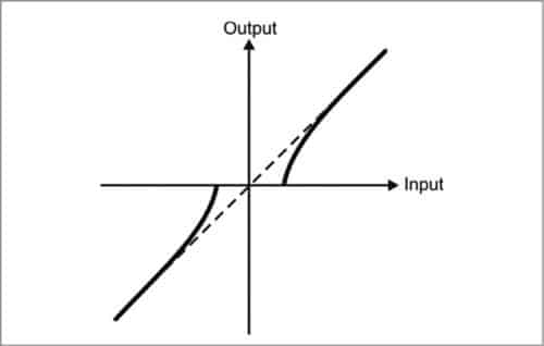
This problem is largely overcome by using forced dithering, in which ring laser cavity is rotated clockwise and counter-clockwise about its axis, using a mechanical spring driven at its resonance frequency. Typically, a peak dither rate of 1Arc-sec/sec is used. Dither frequency is in the range of 400Hz – 500Hz.
Parameters describing RLG’s performance
Important parameters that describe RLG’s performance include bias error, bias drift and instability, scale factor stability and angular random walk.
Bias error
Bias error of a rate gyroscope in general is the output produced by the gyroscope when it is not experiencing any rotation. It is defined as the voltage or percentage of full-scale output, representative of the rotational velocity in °/s as measured by the gyroscope in the absence of any rotation. Bias error is primarily caused by a number of factors, including calibration errors, bias drift, bias variation with temperature and effect of shock or g level.
Bias drift
Bias drift refers to variation of bias error over time, assuming all other factors remain constant. This is a warm-up effect usually caused by the self-heating of electrical and mechanical components of the gyroscope. This effect is more prevalent during the warm-up of the first few seconds and is non-existent after that. It should not be confused with the more colloquial term drift rate.
Bias instability
Bias instability is the fundamental parameter that defines how good or bad the gyroscope is. It is defined as the minimum point on Allan Variance curve, measured in °/hr. It represents the best bias stability achievable in a given gyroscope, with bias averaging taken at the interval defined by Allan Variance minimum.
As an example, bias stability error in the case of Honeywell gyroscope type GG1320 is specified to be ≤0.002°/hr.
Allan Variance technique is a very powerful mathematical method that allows a user to assess the real performance of any gyroscope in relation to the dynamics of its application, taking into account the effects of bias, noise, drift and long-term sensor instability.
Bias instability is always measured by averaging successive data samples. The challenge lies in selecting a suitable time over which to average the sampled data. Averages taken over short time intervals are dominated by noise, while those taken over a longer period are dominated by longer term drift. The technique involves selecting a range of time intervals, typically from 0.01s to 500s, over which to average the data. The standard deviation thus obtained from one averaged time period to the next is calculated and plotted against the averaging interval in log-log form. The resulting graph has a characteristic bathtub shape. By examining this graph, it is possible to compute the key defining characteristics of the gyroscope, namely, angular random walk, bias instability and rate random walk.
Scale factor stability
Scale factor and scale factor stability represent the transfer, or output versus input characteristics of the gyroscope. It measures the signal produced in terms of voltage or bits for a given rotation rate. It is a measure of the slope of the best straight line through the points on a graph representing the gyroscope output against input rotation rate measured over the specified dynamic range of the gyroscope.
As an example, for an analogue gyroscope, it is measured in volts per °/s. Scale factor stability and maximum rate measuring figures for Honeywell gyroscope type GG 1320 are specified to be ≤10PPM and ±500°/s, respectively.
Angular random walk. Angular random walk, or ARW, is a measure of gyroscope noise. It is measured in °/√hr or °/√s. It can be thought of as the standard deviation due to noise while integrating the output of a stationary gyroscope over a period of time. It is inversely proportional to the square root of integration time.
As an illustration, if a gyroscope has an ARW of 1°/√s; ideally speaking, the result of angular position measurement in the ideal case would be zero. But longer the integration time, larger will be the spread of the results away from zero. The spread follows the law of being inversely proportional to the square root of integration time. In the case of Honeywell gyroscope—which is also true for typical inertial-grade gyroscopes—random walk noise is specified to be ≤0.0018°/hr.
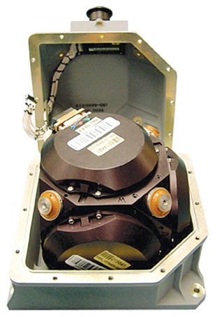
An INS has three orthogonally-placed RLGs to provide measurement capability of rotation in three degrees of freedom. Along with accelerometers, RLGs constitute the INS. Fig. 9 shows one such RLG-based INS package. The system is a high-grade IMU that meets the accuracy requirements of attitude, orientation, position and navigation. The system is characterised by bias stability of 0.1°/hr, scale factor stability of 75PPM and ARW specification equal to 0.028°/√hr.
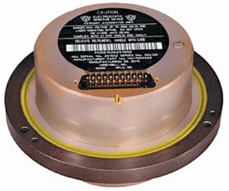
HG9900U from Honeywell Aerospace (Fig. 10) is another navigation-grade IMU. It mainly comprises Honeywell GG1320AN digital laser gyroscopes, Honeywell QA2000 accelerometers and associated electronics.
Laser gyroscopes in this INS package are characterised by one sigma error coefficient of <0.003°/hr (bias), <0.002°/√hr (ARW) and <5ppm (scale factor). Accelerometers are characterised by one sigma error coefficient of <25µg (bias) and <100ppm (scale factor).
HG1700 (Fig. 11) from Honeywell Aerospace is another high-performance, tactical-grade IMU designed for a wide range of guidance and control applications. The IMU package comprises three RLGs, three quartz resonating beam accelerometers and associated electronics, environmentally sealed in rugged aluminium housing. The IMU is available in four different performance grades with one sigma gyro bias of 1°/hr, 2°/hr, 3°/hr and 5°/hr. Corresponding maximum random walk specifications are 0.125°/hr, 1°/√hr, 2°/√hr and 3°/√hr, respectively.
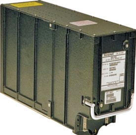
Yet another inertial navigation package from Honeywell, popular with a wide range of passenger and military aircraft, is air data inertial reference system (ADIRS). It is configured around HG-2030 and HG-2050 series air data inertial reference units (ADIRUs). Fig. 12 shows the ADIRS. The ADIRU uses digital RLGs, which, along with quartz accelerometers, provide position and attitude information.
Sigma-95 from SAGEM, France is a high-performance navigation system. It has two variants, namely, Sigma-95L and Sigma-95N. Sigma 95L is a lightweight and compact INS designed for fixed and rotary wing aircraft, offering an excellent performance level. It is particularly adapted to Male unmanned aerial vehicles (UAVs) and pod applications.
With an integrated SAGEM-designed GPS receiver, Sigma 95L can be used either as an autonomous attitude and heading reference system or as a full-size INS. Sigma 95L offers different levels of performance and several modes of alignment to adapt to the different operational needs of users.
Sigma-95N (Fig. 13) is designed for the most demanding applications requiring high navigation and guidance accuracy. It can integrate all available sensors including GPS, Glonass, air data system and so on, in all types of avionic configurations. In pure inertial mode, it offers position accuracy of <0.5 Nm/hr, velocity accuracy of <0.7 m/s, pitch and roll accuracy of <0.03°, and heading accuracy of <0.05°. In hybrid mode, it offers position accuracy of <10m.

GPS ADIRS from SAGEM is another RLG-based navigation package. Sigma-40 inertial navigation system from SAGEM with heading accuracy of <0.05°, and pitch and roll accuracy of <0.02°, and position accuracy of <1.5Nm/24 hours in autonomous navigation mode is an advanced inertial attitude and heading reference system that employs laser gyroscopic technology. It is primarily designed for maritime applications meeting the most demanding navigation and weapon system stabilisation requirements. It is one of the most widely-used naval inertial navigation systems in use on both surface vessels and submarines.
Northrop Grumman’s LTN-101 Flagship integrated global air data inertial navigation unit (GNADIRU) is another major inertial navigation system offering position accuracy of 2.0Nm/hr in pure inertial mode. The inertial sensor in the package combines two 18cm Zero-Lock laser gyroscopes in a single cavity.
LN-100G is another widely-used inertial navigation system from Northrop Grumman. It is a non-dithered INS/GPS, utilising Zero-Lock gyroscope and various GPS solutions.
Fibre-optic gyroscope
Unlike a classical mechanical gyroscope based on the principle of conservation of momentum and very much like RLG, fibre-optic gyroscope (FOG) has virtually no moving parts and no inertial resistance to movement. Operational principle of FOG is also based on Sagnac effect. It consists of a long coil of optical fibre typically a few kilometres in length. It makes use of interference of light to detect mechanical rotation. FOG provides extremely precise rotational rate information, due to its lack of cross-axis sensitivity to vibration, acceleration and shock.
It does not require any starting calibration and consumes relatively less power. FOG can be very compact, as optical fibre lengths as long as a few kilometres can be wrapped around a small diameter coil.
Development of FOGs got a big boost and became a reality in the early 1970s due to technological advances in semiconductor diode lasers and low-loss single-mode optical fibre mainly triggered by the demands of the telecommunications industry.
In the case of a FOG (Fig. 14), two split-laser beams from a single laser are injected into the same fibre but in opposite directions. Due to Sagnac effect, the beam travelling against the rotation experiences a slightly shorter path length delay than the other beam. The resulting differential phase shift is measured through interferometry, thus, translating one component of the angular velocity into a shift of the interference pattern. This is measured photometrically to derive rate information.

Beam splitting optics launch light from a laser diode into two waves propagating in clockwise and counter-clockwise directions, through a coil consisting of many turns of optical fibre. Strength of the interference signal depends on the effective area of the closed optical path, according to Sagnac effect. This is not simply the geometric area of the loop but is enhanced by the number of turns in the coil.
FOG was first proposed by Vali and Shorthill in 1976. Development of both passive interferometer type of FOG (IFOG) and a newer concept, the passive ring resonator FOG (RFOG), are proceeding in many companies and establishments worldwide.
FOG provides extremely precise rotational rate information partly because of its lack of cross-axis sensitivity to vibration, acceleration and shock. It is also because FOG has no moving parts and does not rely on inertial resistance to movement. Hence, it is perhaps the most reliable alternative to the mechanical gyroscope.
Because of their intrinsic reliability, FOGs are used for high-performance space applications. As compared to RLGs, these typically offer a higher resolution but have relatively poorer drift and scale factor performance specifications.
Typically, FOG’s sensitivity figure of 0.1°/hr still does not match anywhere close to the demonstrated RLG sensitivity of better than 0.001°/hr. Also, unlike RLG, where zero beat frequency always means zero angular velocity, in the case of FOG, one needs to determine which indication corresponds to zero angular velocity.
The reason for the success of FOGs lies in its desirable features like lightweight, small size, limited power consumption, projected long life time and low cost. This makes these particularly attractive in applications such as automotive and robotics. These applications call for less demanding performance levels in terms of sensitivity and drift specifications, and where small size and low cost are important considerations.
FOGs are used in a wide variety of applications. Some common ones include inertial navigation, navigation of remotely-operated vehicles (ROVs) and autonomous underwater vehicles (AUVs), surveying, automotive industry and robotics, EO/FLIR/radar stabilisation, line-of-sight tracking and precision pointing, gunfire control systems, platform stabilisation, gyroscope compassing and target acquisition systems, smart munitions and earth observation, scientific and telecommunication satellites.
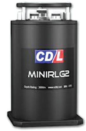
Fig. 15 and 16 show two such FOGs. Fig. 15 shows EMP-1.2K from Emcore Photonics Systems. It provides precise navigation with 1mile/hr accuracy without GPS and fast gyroscope compassing to 1milli-radian. Major performance specifications of the device include short-term and long-term drift stability specifications of 0.005°/hr and 0.01°/hr, respectively, scale factor stability and linearity specifications of 50PPM and 25PPM, respectively. Random walk specification is 0.0015º/√hr.
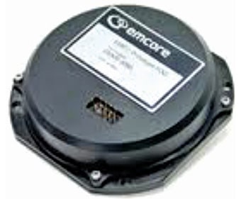
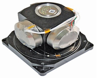
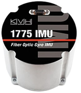
Fig. 16 shows 3-axis FOG assembly from AL Cielo. Sensors can be used in diverse navigation and control applications, such as for stabilisation of missiles, in airborne sensor systems or land vehicle systems. State-of-the-art FOGs compare very closely with the specifications of RLGs.
FOG-based IMUs and INSes from KVH Industries Inc., including 1725 IMU, 1750 IMU, 1775 IMU (Fig. 17), CG-5100 IMU and TG-6000 IMU, offer bias stability specification of better than 0.05°/hr (for 1775 IMU) and maximum input rate specification of ±490° (for 1775 IMU).
Military applications of laser gyroscopes
The technology of laser gyroscopes including both RLGs and FOGs has come of age. Laser gyroscopes are more than a laboratory experiment. Today, these are very strong candidates for being the preferred INS for almost all military and commercial applications, including military and commercial aircraft, tactical and strategic missiles, naval and marine vehicles, land vehicles and weapon platforms, and spacecraft.
Different application areas demand different levels of gyroscopic accuracy. Acceptable range of angular rate error for various military-grade applications employing laser gyroscopes for navigation and guidance is 0.05°/hr – 1.0°/hr (short-range tactical missiles), 0.005°/hr – 0.1°/hr (strategic cruise missiles), 0.0001°/hr – 0.01°/hr (aircraft inertial navigation) and 0.00005°/hr – 0.005°/hr (ballistic missile guidance).
Some representative examples of commercial aircraft using RLG INS include Airbus-320, Airbus-330/340, Airbus-380, Boeing 757-200 and Boeing-777.
RLG INS is also used in fighter aircraft such as F-15E Strike Eagle, F-16 Fighting Falcon, F/A-18 combat jets, F-22 Raptor, Sukhoi-Su-30MKI, HAL-Tejas and B-52H with AMI upgrade, MC-130E Combat Talon-I and MC-130H Combat Talon-II special-mission aircraft, EF-111 Raven electronic warfare aircraft, MH-60R, MH-60S, SH-60F and SH-60B Seahawk helicopters, Trident-I and Trident-II submarine-launched ballistic missiles, Shaurya hypersonic surface-to-surface tactical missile, AGNI-III and AGNI-IV intermediate range ballistic missiles, AGNI-V and AGNI-VI intercontinental ballistic missiles and International Space Station (ISS).
A320, A330, A340 and A380 families of passenger aircraft from Airbus Industries and Boeing’s 737, 757 and 777 family passenger aircraft use Honeywell’s ADIRS. Military aircraft including F-15E, F-16 and F/A-18 also use Honeywell’s GG1320 digital RLG-based INS.
Sukhoi Su-30MKI fighter aircraft employs SAGEM’s Sigma-95 integrated GPS and digital laser gyroscope INS.
Northrop Grumman’s LTN-101 Flagship is also in use in a large number of commercial aircraft of single-aisle and long-range families from Airbus Industries.
SAAB-2000 twin-engine turboprop passenger aircraft built by SAAB, Sweden also uses LTN-101 navigation system.
Northrop Grumman’s LN-100G INS is also used on a wide range of military platforms, including fighter aircraft (F-22 Raptor of Lockheed Martin), trainer aircraft (T-45 Goshawk of Boeing and BAE Systems), transport aircraft (C-130 of Lockheed Martin), pods, missiles, UAVs and unmanned under sea vehicles and helicopters (MH-60 series Seahawk helicopters).
AGNI-III and AGNI-IV intermediate range ballistic missiles and AGNI-V intercontinental ballistic missile (ICBM) in service since 2014 use indigenously-developed RLG-based INS optionally augmented by GPS terminal guidance with possible radar scene correlation.
AGNI-VI ICBM, likely to be inducted in service from 2018-19, will also use RLG-based INS augmented by GLONASS/IRNSS with possible radar scene correlation.
Canister-launched hypersonic surface-to-surface tactical missile uses indigenously-developed RLG-based INS.
Trident-II (UGM-133 D5) submarine-launched intercontinental ballistic missile in use by the UK on Vanguard and the US on Ohio class submarines also employs RLG-based INS. It, along with a stellar reference system, provides CEP of 90 m.
FOG-based 1775 IMU is used in a wide range of applications such as turret and weapon platform stabilisation and pointing, antenna platform positioning and stabilisation, mobile mapping systems, and stabilisation systems for radar, LIDAR and high-speed gimbals.
To be continued…
Dr Anil Kumar Maini was formerly outstanding scientist and director at Laser Science and Technology Centre (DRDO)
Nakul Maini is post graduate in optical engineering from University of Bristol (UK), currently working as senior engineer (product development) at Tek Xplore, New Delhi