


Read Part 4
IPv4 address is a stateful address. This means that, if a node moves from one subnet to another, the user has to either reconfigure the IP address or request for a new IP address from dynamic host configuration protocol. Whereas, IPv6 supports a stateless auto configuration address. Thus, with IPv6, while moving from a subnet to another, a host can generate its own IP address.
IPv4 and IPv6 address spaces are of different sizes. Address notations for the two are also different. IPv6 address of 128 bits is represented by hexadecimal colon notation. 128 bits are divided into eight segments, each of two bytes in length. Each of the segments is separated by a colon. As an example, EFEF:1234:DCEE:7676:1C2C:00FE: AB00:D8B9 represents one IPv6 address. The notion allows to drop leading zeros. As a case, in the example, 00FE can be just FE. Moreover, IPv6 frame provides many flexibilities and options over IPv4 frame. One example of IPv4 address representation of 32 bits is 191.245.245.245, a representation of dot-separated four bytes.

Deployment of IPv6 therefore requires some techniques of compatibility to make IPv6 co-exist and co-operate with the existing vast IPv4 network. After all, it is neither technically-feasible nor economically-viable to upgrade all the existing millions of machines of IPv4 to IPv6.
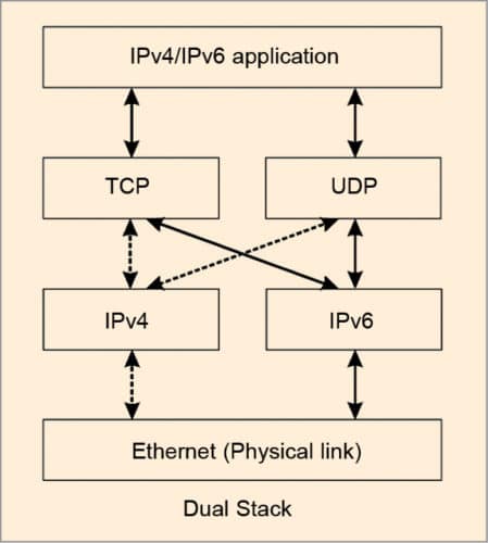
Two schemes used for compatibility are dual stack and tunnelling. Dual stack offers a technique where all nodes in any network are both IPv4- and IPv6-enabled. While deploying, IPv6 nodes can be made backwards-compatible, making it capable of sending IPv4 datagram, too.
However, already existing IPv4 nodes are not capable of sending IPv6 datagram. In dual stack, each node is made IPv6/IPv4-compatible. IPV6 node is made to implement complete IPv4 as well. The node also has the capability to determine whether the next node of routing is IPv4 or IPv6. This is done by the domain name system (DNS). Until and unless the entire world switches to IPv6, dual stack will remain one of the top transition methods for address resolution and a solution for resolving incompatibilities.
In dual stack, any node of IPv6 duly sends IPv6 datagram to the next node, if that node is of IPv6. But if the next node is of IPv4, the received IPv6 datagram is converted to IPv4 datagram before transmitting. By the process of conversion, a lot of information of the original IPv6 datagram like that of flow label, etc is lost. This is a major disadvantage of dual stack.
Even if the next-to-next connected node is of IPv6, under dual stack, as IPv6 is equipped to handle IPv4, datagram will flow as IPv4 datagram and not as original IPv6 datagram. The problem with dual stack may be resolved with tunnelling. Tunnelling allows to run IPv6 over IPv4 without loss of any information that IPv6 carries.
In tunnelling, any node, when transmitting IPv6 datagram to IPv4 node, treats the whole IPv6 datagram as payload. With this payload, a new IPv4 datagram is made. IPv4 nodes treat all IPv6 packets as complete payloads for subsequent transmission in tunnelling. In the stated process, information of IPv6 datagram is preserved, but overhead increases. As a result, coding efficiency of the datagram, so framed, decreases. Thus, trade-off between dual stack and tunnelling is loss of information versus decreased coding efficiency.
However, as under tunnelling, IPv6 datagram is repackaged for transmission over IPv4, it is done with an encryption standard to hide the nature of the original datagram while running through the tunnel.
Bootstrap protocol
Reverse address resolution protocol (RARP) is used to obtain the information of the IP address (logical address) corresponding to a given physical address of the machine. RARP does not provide the router or gateway address, server address, etc.
Bootstrap protocol (BOOTP) is used to provide additional information to a caller. BOOTP message goes as a payload of UDP layer. The message format is shown in Fig. 2. Fields in the message are as follows:
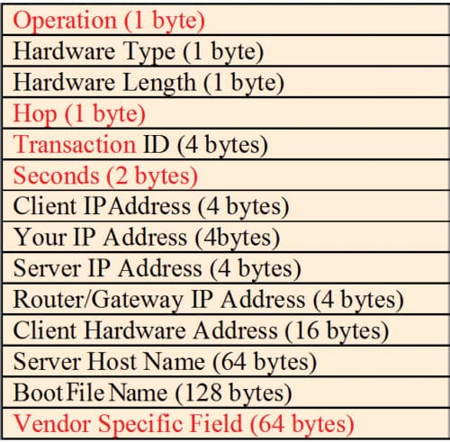
- Operation field. Set 1 and 2, respectively, for request and reply
- Hop field. Set to 0 in the request message. When the message is passed from one server to another, hop count is incremented by one
- Transaction ID field. Used for sequential co-ordination between request and reply messages, just like the sequence number in IP datagram
- Seconds field. Used to count time in seconds, since the host starts BOOTP
- Others field. Self-explanatory; vendor-specific fields are not yet standardised
When a device (say, computer) connected to a network is powered up and boots its operating system, the system generates a broadcast BOOTP message. The message is a request for an IP address. A BOOTP configuration server assigns the IP address based on request. With the start of BOOTP procedure, when a request is sent to the server, a timer is turned on. If no reply is received within the defined time period, BOOTP should attempt retransmission. BOOTP is implemented with UDP as transport protocol. It operates only with IPv4 networks.
Dynamic host configuration protocol
IPv4 address is a stateful address. This means that, if a node moves from one subnet to another, the user has to either reconfigure the IP address or request for a new IP address from dynamic host configuration protocol (DHCP). DHCP is a network management protocol used over UDP/IP networks. A DHCP server dynamically assigns IP address and other network parameters to each of the devices connected to a network. With DHCP, an IP address is leased out to a device (host or computer) for a defined period of time.
Whereas, IPv6 supports a stateless auto configuration address. Thus, with IPv6, while moving from a subnet to another, a host can generate its own IP address. This is done by the host by adding its Media Access Control (MAC)/physical address to the subnet prefix.
IPv6 also supports multiple addresses for each host. Three types of address may be made: valid, deprecated or invalid.
- With valid address, new and existing communication may be done.
- With deprecated address, existing communication may be done.
- With invalid address, no communication is done.
When a host attempts to get an IP address, a DHCP discover message (Fig. 3) is broadcast over the physical network with broadcast IP address 255.255.255.25. The discover message is received by all routers and other hosts, which they ignore. Only the DHCP server or router replies. Other routers discard the discover message. This prevents the entire Internet from being flooded with discover message.
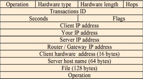
DHCP server in the network replies with DHCP offer message. The offer message provides an IP address and other information related to configuration. Every network need not have a DHCP server. A network may have DHCP relay agent, which requests the remote server for reply to be subsequently sent to the requesting host. If the requesting host receives a number of offers from a number of DHCP servers, it will accept one offer and acknowledge the same to the corresponding server, which then acknowledges the reply of the host. Then, the host uses the IP address for communication.
Mobile IP
Mobile IP is the real next extension of mobile voice communication. Advances in wireless network technology have immensely changed various parameters like process, method, perception, quality and characteristics of voice communication. Consequently, developments in wireless data protocols have paved the way for mobile IP for data communication.
What cellular technology, Global System for Mobile (GSM) communication or cellphone do for telephony, mobile IP will do for TCP/IP-based mode of data transport. IP Internet has become ubiquitous in wireline environments. Support of mobility is already available today in some forms using satellite access to an Internet service provider (ISP). But satellites provide access to just one ISP at a time, and only as long as the user is within the satellite’s footprint.
Mobile IP provides a platform for carriers to offer assured and continuous access to the Internet or a private IP-based network. IP datagram is a packet with data plus header fields of different layers of the Internet architecture. This is like a letter that contains a message plus other data like sender and receiver names, addresses, pin codes, etc.
An IP datagram carries both source and destination addresses of data. Thus, if source or destination changes, the connection becomes void until and unless the changed IP address is notified to all users.
In conventional wired Internet connectivity, when a user gets connected to the Internet, the point of attachment is made through an address known as IP address. This IP address is attached to a fixed plugged-in position.
In wireless connectivity, when a user is connected, he or she is connected to an IP address that is valid over the coverage area cell of wireless connectivity. The mobile user changes location dynamically with time. Thus, plugged-in fixed IP address of the wired Internet will be of no use to support connectivity to the mobile user.
On the other hand, there is no guarantee that mobility will be limited to the coverage area in case of wireless connectivity. IP address has to change when the mobile user moves away from own coverage or cell area to remain in connectivity.
One simple solution is to not assign a fixed IP address. There is a requirement to dynamically change the IP address. A new protocol called DHCP is made to resolve the stated issue. DHCP allows the intended user to obtain a temporary IP address dynamically. Like when one goes on deputation, one is allotted a temporary office/residential address.
This is a simple management solution. But a temporary address has two major disadvantages: temporary address notification and system upgradation. Other nodes cannot easily originate transmissions to the mobile node (MN) as these do not know about its new IP address. And each time a mobile computer obtains a new IP address, Internet client software applications must be restarted.
Again, temporary addresses do not let a mobile user roam seamlessly from one IP subnet area to another. This creates a bottleneck, especially for wireless local area networks (LANs). As an example, a doctor with a wireless LAN connection needs to maintain IP connections throughout the hospital as he or she accesses patient records. This is where the need for a different solution by mobile IP arises.
Mobile IP enables mobile users to stay connected to the Internet regardless of their location and without changing their IP address. It allows them a fixed IP address for being connected to any IP subnet and immediately be reachable from the Internet.
Mobile IP is an extension of conventional IP and makes mobility transparent to higher layers of the Internet architecture. In fact, it is not just wireless connectivity, it a mobile connectivity that supports seamless machine mobility with the support of Internet+DHCP.
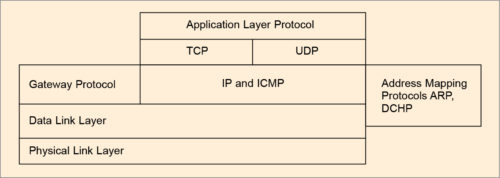
Relational feature of DHCP, ICMP, ARP over basic TCP/UDP is portrayed in Fig. 4. Internet Engineering Task Force (IETF) defines mobile computer as a device used to carry data while users move from one network to another while maintaining their permanent IP address.
An IP address uniquely identifies physical attachment to the subnet of Internet connectivity. When a source and a destination communicate over the Internet, they generally employ TCP for an end-to-end logical connection. When this logical connection is created, a TCP port number is assigned at both source and destination ends so that these two hosts remain in connection. Every end-to-end TCP logical connection is uniquely identified by four values: source IP address, source TCP port, destination IP address and destination TCP port. These remain fixed and static for the duration of the connection.
The basic problem with mobile node (MN) is that it may move from network to network. Therefore the challenge in mobile IP is to manage MN’s IP address while dynamically changing location so that MN can always communicate with its permanent IP address. The solution is made with the proposed working principle of mobile IP, illustrated in Fig.5.
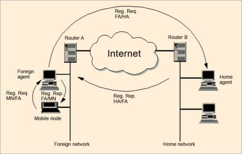
A node that roams and changes its position dynamically but keeps on communicating with any other system in the Internet as long as link-layer connectivity is given is defined as MN. Home network (HN) is the subnet MN longs for. MN has its IP address with the home subnet. No mobile IP support is needed when MN communicates within HN. Foreign network (FN) is the subnet except HN. The current subnet is that in which MN node is visiting currently.
MNs are assigned two IP addresses. The first is called home address. Home IP address is a static address used to identify the end-to-end connection, and is used by MN when connected to its HN.
The second address is care of address (COA). It is not static. It is a dynamic address used for packet routing only and is used by MN by FN. CAO changes every time MN changes to a new sub-network. All IP datagrams sent to MN are delivered to COA, and not directly to the static IP address when MN is in FN.
There are two agents: foreign agent and home agent. These are known as mobility agents. These are mobile-IP-aware servers or routers that know where MN is actually connected. Home agent is HN’s mobile IP agent, which has the responsibility of forwarding MN’s packets to FN where MN is actually connected.
Foreign agent is responsible for delivering packets to the transient MN. It provides many services to MN during its visit to FN. It tracks COA, acting as the tunnel endpoint and forwarding packets to MN. Foreign agent is located in FN. It is the default router for MN when it is in FN. It also provides security services to MN.
Home agent is located in HN. It forwards IP packets to MN via COA. It maintains linked coordination between the home IP address of MN and its COA. A tunnel is established by home agent between itself and a reachable point (usually COA) for MN when it is in FN.
Working principle of mobile IP.
The working principle of routing IP datagram in fixed Internet makes use of routers. Routers make use of IP address of IP datagram to route data from a source node to destination node.
IP address has two parts: network ID and host ID. Network ID identifies the sub-network on which the host is connected. Host ID is the host identification number.
Network ID is used by routers to move the datagram from one sub-network to another. Final router in the target sub-network moves the packet to a particular host based on host ID. MN communicates with another host or node on the Internet, mobile or not. The entire mobile IP process is transparent. MN is known to any other node or host by home address of MN wherever MN is physically present.
All packets between any other node or host and MN use MN’s home address, regardless of whether MN is in HN or FN. COA is only used for communication with mobility agents and is never seen by any node or host while communicating with MN.
One of the important design goals of mobile IP is to make mobility possible without major changes to the large, existing installed base of IPv4, particularly routing infrastructure. The principle on which mobile IP works is based on three steps: data transfer, getting recognition (discovery) and registration.
Data transfer phase is made of encapsulation and tunnelling. It works as follows:
Packet from static node to MN.
Any node or host (A) can send packet to MN (B), but it has to do so with the home address of MN. IP datagram will carry IP address of A as source and home address of B as destination address.
Incoming packet is intercepted by the home agent in HN. If MN is on home network, home agent delivers the packet locally. If MN is on FN, home agent forwards the packet to the foreign agent by the process of encapsulation and tunnelling. Home agent encapsulates the whole incoming packet into a new IP packet with B’s COA as destination address and then transmits the encapsulated packet as one IP datagram. The method of using an outer different destination IP address is known as tunnelling.
Foreign agent on receiving the encapsulated packet strips off the outer IP header. This is called decapsulation. It then encapsulates the decapsulated original IP datagram in the network-level protocol data unit (PDU), for example logical link control (LLC) frame of LAN, and delivers the packet to A on FN.
Packets from MN to any other static node.
Packets from MN (B) to the any other node or host (A) are sent via home agent when MN is in HN.
Packets from MN to any other node or host are sent via foreign agent when MN is in FN.
A mix of techniques described above is used from exchange of packets between two different MNs.
The principle, as stated above, will work only when MN is available to register its mobility with the foreign agent in FN. It has to register when it enters FN as well as when it leaves FN. This is done by a process called getting recognition (discovery) and registration.
Getting recognition is a process by which MN registers its location with appropriate agent, either home or foreign. MN finds a mobility agent by two methods: agent advertisement and agent solicitation message.
Agent advertisement is a process by which foreign and home agents exchange their respective presence periodically using agent advertisement message. MN in a subnet then receives agent advertisements from either its home or foreign agent. This is one way for MN to discover its location.
In second method, MN may use agent solicitation message for a quick reply for locating the agent. In either case, this process allows MN to identify its current mobility agents and then obtain one or more COAs.
Using this method, it also learns about any special services provided by a foreign agent and determines whether it is connected to its HN or FN.
Registration is a process by which having received COA, MN has to register with home agent. As MN roams, it is connected to a series of one or more FNs. The main purpose of this registration is to inform home agent of the current location of MN for correct forwarding of packets. This process provides a link between home and COAs, and defines the lifetime of registration.
This is done by sending binding updates from MN to home agent. For this three values, namely, MN home static IP address, COA and lifetime are used. Home agent sends a registration reply to foreign agent, who forwards this reply to MN. This operation is shown in Fig. 5. Encryption is used to authenticate the registration information.
A key concern with registration is security. The default authentication algorithm uses key-based MD5 (message digest version 5) to produce a 128-bit message digest.
When MN is in FN and is registered with home agent, home agent will work as a proxy for MN. When HN receives packets addressed to MN, it intercepts those packets (using Proxy ARP) and encapsulates them with overhead COA.
Encapsulated packet is then sent to COA, which is the current IP address that foreign agent is registered with MN. Foreign agent will decapsulate those packets and forward them to MN, because it knows exactly where MN is. Encapsulation is the method used by home agent to deliver information to MN by putting an extra IP header on top of the packet.
Tunnelling is a process by which the encapsulated packet is sent to MN when it in FN (Fig. 5). Two forms of encapsulation are specified in related standards request.
Getting recognition (discovery) makes use of ICMP. This is done by appending appropriate extension to ICMP headers. ICMP is a connection-less protocol that suits this operation. Registration requires a protocol that communicates between an application on MN and that in the home agent. Thus, it requires a transport-level protocol. As it is a simple request-and-response transaction, overhead of connection-oriented TCP is not required. Thus, UDP is used as the transport protocol for registration. Tunnelling is done at IP level.
This article is dedicated by the author to Prof. A.K. Chowdhury, who is known as the father of computer science in India.
Read Part 6
Prof. Chandan Tilak Bhunia is PhD in computer engineering from Jadavpur University. He is also fellow of Institution of Electronics and Telecommunication Engineers, fellow of Institution of Engineers (India) and fellow of Computer Society of India.

