Part 1 and Part 2 covered particle beam weapons and their technology, respectively. In this part we look at high-power microwaves (HPMs).
In the era dominated by electronic warfare and smartweapons systems facilitated by advances in electronics technologies, military planners and strategists have always been on the look out to acquire improved capabilities in countering artillery fire, providing self-protection to aircraft and credible ship defence against cruise missiles, destruction or disruption of command and control assets, suppression of enemy air defence systems, space control and security and so on.
HPM weapon systems with their speed-of-light delivery, all-weather capability to destroy an adversary’s electronics systems, area coverage of multiple targets, minimum collateral damage, simplified tracking and beam pointing and a deep magazine address most of the requirements of military commanders of the day.

HPM weapons generate an intense blast of microwave energy strong enough to overload electrical circuitry, inducing currents large enough to temporarily disrupt electronic systems or permanently damage integrated circuits, causing these to fail minutes, days or even weeks later. The microwave blast may even melt the circuitry in some cases. Humans exposed to the blast of an HPM weapon remain unharmed and might not even know that they have been hit.
A number of technological challenges need to be addressed to come to the level of a deployable HPM weapon possessing all of the above features. These include development of compact high-peak-power or average-power HPM sources, compact high-gain ultra-wideband antennae, compact and efficient pulse power drivers, predictive models for HPM effects and lethality to create a comprehensive database on effects of such a radiation on a wide range of land, sea, air and space based military assets and system integration to meet the requirements of a variety of military platforms such as fixed-wing and rotary aircraft, land vehicle, aircraft pods, naval combatants, unmanned aerial vehicles and so on.
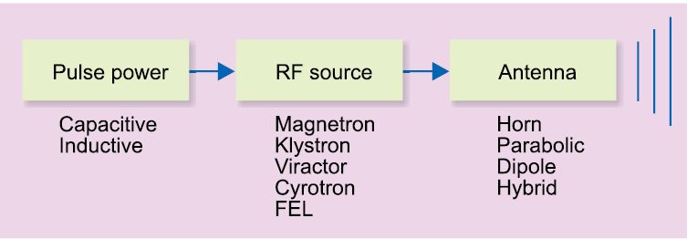
An HPM weapon essentially comprises a pulse power source that drives the microwave source, HPM source and a transmitting antenna that directs the microwaves towards the target and acts as an interface between the microwave source and the atmosphere.
Besides these, HPM weapons also include tracking, aiming and control systems. The microwave power generated by the weapon, beam characteristics and target vulnerabilities together determine the effective operational range of the HPM weapon system.
The weapon is designed to disrupt, degrade or destroy electronics of the target by radiating electromagnetic energy in the microwave frequency band. Microwave frequencies ranges from 300MHz to 300GHz. HPM weapons under development occupy the frequency range of 500MHz to 3GHz. Frequencies around 100GHz have been exploited to build non-lethal weapons due to the significant effects this frequency has on human beings. This is primarily due to the coupling effects and generic electronic system vulnerabilities.

HPM weapons are broadly categorised as narrow-band HPM and ultra-wide-band HPM. While narrow-band HPM weapons radiate all their energy within few per cent of the centre frequency, which is in the range of tens to hundreds of megahertz, an ultra-wide-band HPM radiates microwave energy over a bandwidth in the range of hundreds of MHz to several gigahertz.
Ideally, HPM weapon systems could be used to replace precision-guided munitions to disable or destroy high-value targets or installations located in populated areas with minimised risk of human casualties.
Other application under consideration is suppression of enemy air defence. Most air defence systems are highly susceptible to HPMs. Surface-to-air missiles contain highly-sensitive guidance systems and fire control is usually radar-controlled. Environmentally-dangerous targets such as chemical and biological weapon-production facilities could be targeted more effectively by HPMs without the fear of releasing deadly toxins into the atmosphere.
Types of HPM weapons
As mentioned earlier, HPM weapons are generally categorised as narrow-band HPM and ultra-wide-band HPM. Narrow-band HPM weapons produce an HPM output in a narrow band of frequencies with the bandwidth equal to only a few per cent of the centre frequency. These weapons are capable of generating relatively-higher output power levels as compared to ultra-wide-band HPM weapons.
Narrow-band HPM systems are effective only on a given class of targets that would absorb the frequency emitted by the system. Therefore in the case of a narrow-band HPM, knowledge of absorption by the target material as a function of frequency and aspect angle is an advantage. Frequency absorption data may be generated by scanning the target with a tunable low-energy microwave source and evaluating the reflected signals for missing frequencies. Missing frequencies in this case are those that are heavily absorbed by the target material.
Narrow-band HPM weapons have the advantage of better transmission characteristics and fewer problems with fratricide. Limitations include their susceptibility to countermeasures such as target hardening and prior knowledge of the threat required to choose the optimum microwave frequency.
Ultra-wide-band HPM weapons, on the other hand, radiate over a broad frequency range but deliver comparatively less microwave energy at specific frequencies. While, narrow-band HPM weapons are capable of defeating only well-defined targets or class of targets, ultra-wide-band weapons are intended for use against a wide range of targets.
Ultra-wide-band HPM weapons do not require any prior information on the target’s absorption characteristics and provide a broad capability range. Due to comparatively lower radiated microwave power and poorer transmission characteristics than narrow-band HPM weapons, these have shorter operational ranges.
Components of an HPM weapon system
As outlined earlier, an HPM weapon system essentially comprises a pulsed power source, a source of microwave energy and a transmitting antenna (Fig. 1). The pulsed power source further comprises a power supply and a pulse generator.
Pulse power generators. Pulse power generators that drive HPM sources are generally required to deliver short, intense electrical pulses of 1MV or more with pulse duration up to 1µs. One way to generate the required pulses is by using capacitor banks that transform a slowly-rising low-voltage signal into a fast-rising high-voltage sigPulse power generators. Pulse power generators that drive HPM sources are generally required to deliver short, intense electrical pulses of 1MV or more with pulse duration up to 1µs. One way to generate the required pulses is by using capacitor banks that transform a slowly-rising low-voltage signal into a fast-rising high-voltage signalnal.

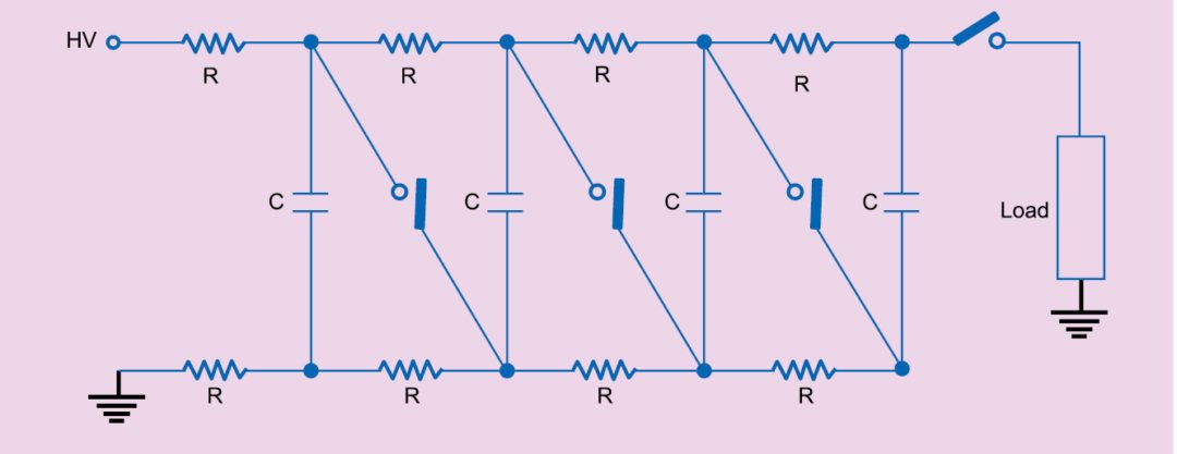
A common capacitor bank configuration is Marx bank (Fig. 2) where the capacitors in the bank are connected in parallel during the charging process and switched to a series connection during discharge.
The series connection multiplies the voltage by the number of capacitors in Marx bank. Resistive charging is slow and therefore limits repetition rate. Inductors could also be used in place of resistors. Inductor charging is preferred for higher repetition rates of a few hertz or more. If Marx bank has n capacitors with each charged to a voltage V from a DC power supply, voltage delivered to the load during discharge would theoretically be equal to n×V.
Spark gaps are used as switches and breakdown voltage of spark gaps is kept higher than the voltage V across each capacitor. Initially, all capacitors are in parallel and are charged to a voltage V. Spark gaps are in open state. In order to initiate discharge, the first spark gap is externally triggered to the breakdown state connecting the first two capacitors in series and thereby raising the voltage across the second spark gap to 2V.
The second gap also goes to breakdown state and the process continues till a voltage pulse with amplitude equal to n×V is applied across the load.
One such Marx generator designed to drive HPM sources is APELC MG20-22C-2000PF from Applied Physical Electronics LC. This megavolt-class Marx generator with its 18-ohm source impedance is specifically designed to drive low-impedance loads. With a 50kV charge voltage it delivers a 500kV, 1.1kJ pulse into a matched load with a peak power of more than 12GW. This generator uses low-impedance, parallel-switched topology, which makes it well-suited for a wide variety of HPM applications.
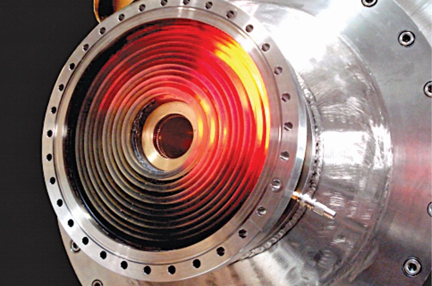
Another Marx generator from the same company is MG30-3C-100nF (Fig. 3) that is capable of storing a maximum of 1.8kJ and can deliver 300kV to a matched load. This Marx generator has low impedance of 33ohms and is axially compact in order to drive HPM antennae on remote platforms. Maximum peak power and repetition rate specifications are 5GW and 10Hz, respectively.
The other method is to use a flux-compression generator (Fig. 4). In such a generator, a magnetic coil is compressed either by explosive or magnetic forces leading to rapidly-rising current pulse. In an explosively-driven flux-compression generator, chemical energy of the explosives is to be partially converted into the energy of an intense magnetic field surrounded by a correspondingly large electric current.
Explosively-driven flux-compression generators are for one-time use only as the equipment gets destroyed during operation.
Such a flux-compression generator constitutes an important component of an e-bomb. It consists of a metal cylinder called armature, which is surrounded by a coil of wire called stator winding. The armature cylinder is filled with high explosive and a sturdy jacket surrounds the entire device. The stator winding and the armature cylinder are separated by empty space. A Marx bank type power source used to drive the stator winding is also a part of the bomb.
An electrical current through the stator winding generates an intense magnetic field. The explosive, when triggered, travels as a wave through the middle of the armature cylinder, forcing it to come in contact with the stator winding, thereby creating a short-circuit. The moving short-circuit compresses the magnetic field, thereby generating an intense electromagnetic burst.
Another common option is to replace the flux-compression generator by a pulse-forming network.
Caution may be exercised to ensure that the pulsed power source delivers a well-matched signal with regards to voltage and impedance. An impedance mismatch between the driver signal and the HPM source leads to poor energy transfer to the HPM source, more so if impedance of the source was lower than impedance of the driver.
Choice of the pulsed power source is therefore largely governed by the type of HPM source to be used. Conventional microwave sources used in radars, etc and HPM sources operate at different voltage and impedance levels. While conventional microwave sources typically operate on relatively low-voltage and high-impedance levels, HPM sources operate at relatively higher-voltage and lower-impedance levels.
HPM sources. HPM sources are broadly classified as impulsive sources and linear beam sources. In the case of impulsive sources, pulsed microwave energy is generated by charging the antenna, a transmission line or a tuned circuit directly, and making these ring for one or several cycles by closing a switch.

In the case of linear beam sources, microwave energy is generated by converting kinetic energy of an electron beam into electromagnetic energy of the microwave beam. While various ultra-wide-band sources are examples of impulsive sources, examples of linear beam sources include klystrons, travelling-wave tubes, backward-wave oscillators, magnetrons, cross-field amplifiers, split-cavity oscillators, virtual-cathode oscillators, gyrotrons, free-electron lasers and orbitron microwave masers.
Antennae. An antenna acts as an interface between the transmitter output and the medium which the radiated electromagnetic waves have to propagate through. In the case of an HPM weapon system too, it is an interface between the HPM source output and the surrounding atmosphere. Antennae play a crucial role in the HPM system design. Some of the important factors that need to be addressed by HPM antennae include directivity, ultra-wide bandwidth, feed-to-antenna coupling efficiency and compactness.

Directivity plays an important role. Since the HPM equipment is in close proximity to the antenna, the equipment may suffer damage if radiated energy is not radiated effectively. An HPM signal, due to its very short pulse duration, inherently has very wide bandwidth. The antenna therefore has to meet the stringent requirements of handling this ultra-wide bandwidth.
Another important requirement is that of proper matching between the feed and the radiating element, lest the resultant standing waves would cause voltage breakdown. HPM antennae tend to be massive in order to avoid voltage breakdown at operating electric field levels. To meet the increasing requirements of having HPM weapon systems on smaller platforms, antenna size can play an important role.
Antenna shape is also an issue as it influences to a great extent whether air breakdown phenomenon is an issue or not at high power levels. Horn antennae and antenna arrays are the promising candidates for HPM sources with the former presently being the most commonly-used type. Different types of horn antennae including conical, circular, rectangular, corrugated and half-oval, and TEM horn antennae are used with a particular design depending upon the intended application.
Capabilities and limitations of HPM weaponisation
A number of technological and operational issues need to be addressed if HPMs were to move out of the confines of research and application laboratories to become serious contenders as operational weapons for defensive and offensive roles. These include issues of weapon systems’ compactness and efficiency to suit a range of military platforms, issues related to antenna aperture to get desired operational ranges and peak-versus-average powers. Target acquisition, tracking and beam-pointing technologies and lethality assessment are other important factors.
Key advantages of HPM based directed energy weapons include speed-of-light delivery, all-weather capability, effectiveness over large areas, scalable effects, deep magazines and minimised collateral damage.
HPMs are speed-of-light weapons with essentially no time-of-flight as compared to finite travel time of conventional kinetic energy weapons. A supersonic missile travelling at 6Mach speed would take a flight time of about 50 seconds to hit a target 300km away. On the other hand, an HPM weapon could hit the same target in a millisecond or so. This feature is particularly suitable for attacking fast-moving targets.
Unlike high-energy laser weapons (to be described later), which are clear-weather weapons, HPM weapons are not adversely affected by weather and atmospheric conditions. For all practical purposes, these are all-weather weapons.
HPM weapons are area weapons unlike high-energy laser weapons that are point weapons. The footprint depends on the weapon’s power output, distance from the target and beam divergence. These affect all vulnerable equipment that comes within their lethal footprint (Fig. 5).
HPM weapons are ideally suited for targeting in urban environment due to minimised collateral damage. Some collateral damage may occur if friendly or civilian electrical systems are also in the footprint. HPM weapons have a deep magazine. Unlike conventional kinetic energy weapons that are single-shot weapons, HPM weapons can operate any number of times as long as there is power source. This also implies reduced logistics cost and cost per shot.
HPM weapons’ effects are scalable. Depending upon the magnitude of energy deposited on the target, the effects may be non-lethal or lethal. Active Denial System of the USA is a non-lethal HPM system designed for area denial, perimeter security and crowd control. It operates by heating the target’s surface. In anti-personnel role, it is the skin of targeted human subjects. Also, HPM weapons have the potential of jamming the targeted system without any knowledge about the RF output of the system.
In the case of an HPM attack, targeted system recovery is extremely difficult as it may require component or sub-system-level troubleshooting.HPM weapons are highly effective against deeply-buried bunkers by targeting vulnerable electronic systems such as communications, power and air ventilation systems that support these bunkers.
Major limitations of HPM weapons include relatively shorter operational ranges, difficulty of damage assessment and likelihood of damage to friendly, unprotected systems.
HPM weapons are area weapons and therefore adversely affect all unprotected electronic systems within their lethal footprint. These could include civilian and friendly systems, which could be protected by using proper shielding. Proper planning before an HPM attack could prevent unintended damage to friendly assets.
In the case of an HPM weapon attack, target damage assessment is very difficult as there are no signs of any physical destruction. Just because a system has stopped operating or emitting does not mean it has been affected by an HPM attack. Both absence and presence of emission from the targeted system does not reliably establish the efficacy of attack. However, advanced techniques may be used to measure second- and third-order effects to corroborate the results and enhance attack assessment.
HPM weapons have relatively shorter ranges as compared to high-energy laser weapons. In case of an HPM weapon system, range is proportional to both power output and antenna size. However, at sufficiently high microwave power levels, atmosphere at the antenna aperture becomes plasma, a phenomenon called atmospheric breakdown.
Plasma density increases with time duration of HPM pulses, eventually reaching the point where plasma reflects and absorbs RF energy. This not only renders the beam ineffective but also creates a shielding problem for the delivery platform.
Once atmospheric breakdown occurs, operational range can be increased only by increasing the antenna aperture, which may not be possible for portable or airborne designs.
For applications where portability is not a requirement and size is not a limiting factor, one can increase the effective aperture size and power on the target by using phase-locking techniques and combining multiple transmitters.
Another approach may be adopting designs that integrate antennae into the skin of the system, which allows aperture to be as large as the delivery platform. One such application scenario is that of point defence where the target is travelling towards the weapon system rather than weapon travelling towards the target. Ranets-E and Vigilant Eagle HPM systems are examples of such systems.
In the next part we will learn about e-bombs and representative HPM weapon systems.
To be continued…
Dr Anil Kumar Maini is former director, Laser Science and Technology Centre, a premier laser and optoelectronics research and development laboratory of Defence Research and Development Organisation of Ministry of Defence


