


In the first part of this article we covered SENSORIS innovation platform, and the steps needed to make a self-driving car possible. In this part we shall cover lidar and the rest.
Lidar, which stands for light detection and ranging, consists of a cone- or puck-shaped device that projects lasers that bounce off objects to create a high-resolution map of the environment in real time. In addition to helping driverless cars to see, lidar is used to create fast and accurate 3D scans of landscapes, buildings, cultural heritage sites and foliage. It is also used to help create Radiohead’s House of Cards music video.
When positioned on top of a vehicle, it can scan up to 60 metres in all directions, generating precise 3D maps of the car’s surroundings and ensuring the vehicle can avoid obstacles and collisions. It is expensive, but it provides visibility where other sensors might fail. Lidar is the best of both the worlds—it sits between cameras and the radar, and can detect both distance and objects, and can make out the shape of those objects.

Radars, on the other hand, are good at detecting objects and how far away these are, but do not offer any information about the shape or size of the object. The radar in Tesla Model S likely did detect the truck it collided into, but the system is designed to tune out objects that might look like overhead road signs to prevent it from events.
The integration Richard Wallace of Tesla referred to is the algorithms and intelligence that control the way different sensors work together. Lidar and vehicle-to-vehicle communication, where each car communicates its location to others nearby, will both play a key role in building safer self-driving fleets.
Lidar units that Google uses in its self-driving cars cost up to US$ 70,000 per unit, though there are now units that cost as little as US$ 250. This could make it more accessible for the mass market.
Sensoris data standard will enable driverless connected vehicles to prepare for changing conditions and hazards well before the vehicle, be it a truck or car, can see these. In addition to the various sensors such as lidar systems, cameras and ultrasonics required in driverless vehicles, the map is a virtual sensor that provides vital information to the vehicle about the road and terrain ahead and what it is likely to encounter over the hill or around the corner where the sensors cannot currently see.
But driverless vehicles need more than just these sensors to provide a smooth and safe driving experience. These need to communicate with all other vehicles on the road by sending, receiving, interpreting and responding to live route conditions in real time. Sharing of data can apply to all modes of transport including bikes, buses, trams and trains; and not just cars or trucks.
To get this right, there is simply insufficient information available from one car brand or model, and to enjoy the huge benefits of the new innovation and its reduction in emissions and congestion, we have to think both on a new scale and collaboratively.
First of all, a lidar sensor is typically installed on self-driving vehicles that emit eye-safe laser light as the sensor head rotates. Unlike streetlight cameras, these systems do not read licence plates, and laser light scatters/reflects off the windshield and surrounding objects.
Mobile active and passive sensors.
This approach can place very inexpensive smart RF transceiver systems in millions of new and existing cars that communicate with a stationary light-pole-mounted lidar system. The easy-to-integrate embedded sensor exchanges RF signals and display in-dash and audible warnings to drivers, while the lidar system maps the local area. Like radar detectors, it could have a huge potential market and also allow for faster technology disruption on a wider scale. It could also help accumulate millions of hours of actual use statistics nationwide in hundreds of cities and municipalities at a much faster pace.
Widespread embedded safety alert systems.
This approach allows ad-hoc technology disruptors and creative individuals to embed these sensors more broadly in smaller and safer stationary use cases, creating smart networks of lidar and embedded sensors.
A public safety system like this might provide a new kind of stationary collision-avoidance and weather systems for congested roads, toll ways, on-ramps/off-ramps, alerts for drivers about pedestrians, school crossings, bikes, narrowed lanes, accident avoidance, construction and wildlife. By sensing the automobile behaviour, it could alert drivers of roadway weather conditions (black ice, ice on bridges, snow conditions, slick roads, etc). All modes of traffic and weather conditions could be understood more deeply. In this case, any new technology ideas in these application areas would be better than none—the situation we have today.These sensor systems are continuing to get smaller and will be ideal for a number of embedded applications. Instruments and techniques such as the compass, sextant, LORAN radiolocation and dead reckoning. These are among those that have been used with varying degrees of accuracy, consistency and availability.
For autonomous vehicles, the navigation and guidance sub-system must always be active and keep checking how the vehicles are doing versus the goal. For example, if the originally optimum route has unexpected diversions, the path must be re-computed in real time to avoid going in the wrong direction. Since the vehicles are obviously constrained to roadways, this takes much more computational effort than simply drawing a straight line between A and B.
The primary sub-system used for navigation and guidance is based on a GPS receiver, which computes the present position based on complex analysis of signals received from at least four constellations of over 60 low-orbit satellites. A GPS system can provide location accuracy of the order of one metre (actual number depends on many subtle issues), which is a good start for the vehicle. Note that, for a driver, who hopes to hop in the car and get going, a GPS receiver takes between 30 and 60 seconds to establish initial position, so the autonomous vehicle must delay its departure until this first fix is computed.
GPS sub-systems are now available as sophisticated system-on-chip (SoC) ICs or multi-chip chipsets that require only power and antenna, and include an embedded, application-specific compute engine to perform intensive calculations. Although many of these ICs have an internal RF preamp for the 1.5GHz GPS signal, many vehicles opt to put the antenna on the roof with a co-located low-noise amplifier (LNA) or RF preamplifier, and locate the GPS circuitry in a more convenient location within the vehicle. The antenna must have right-hand circular polarisation characteristics to match the polarisation of GPS signals, and it can be a ceramic-chip unit, a small wound stub design or have a different configuration.
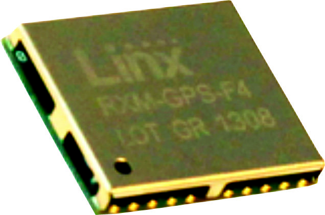
An example of a GPS module is RXM-GPS-F4-T from Linx Technologies, shown in Fig. 4. This 18mm×13mm×2.2mm surface-mount unit requires a single 1.8V supply at 33mA, and can acquire and track up to 48 satellites simultaneously—more channels allow the GPS to see and capture more data and, thus, yield better results and fewer dropouts. Its sensitive front-end requires signal strength of -159.5dBm for operation. After it computes locations based on GPS received signals, it provides output data to the system processor via the serial interface using industry-standard National Marine Electronics Association message format.
While GPS is an essential function for autonomous vehicles, it is not sufficient by itself. The GPS signal is blocked by canyons, tunnels, radio interferences and other factors, and these outages can last for many minutes. To supplement the GPS, the autonomous vehicle uses inertial guidance that requires no external signal of any type. The inertial measurement unit (IMU) consists of a platform fixed to the vehicle, and this platform has three gyroscopes and three accelerometers, one pair oriented each for orthogonal x, y and z axes. These sensors provide data on the rotational and linear motion of the platform, which is then used to calculate the motion and position of the vehicle, regardless of speed or any sort of signal obstruction. Note that, an IMU cannot tell you where you are, only the motion, so the initial location of the vehicle must be determined by the GPS or entered manually.
The in-vehicle IMU would not be practical without the development of MEMS based gyroscopes and accelerometers. The historical and fully-refined IMU is based on a spinning-wheel gyroscope and a gimbaled platform, which has served many applications quite well (missile guidance/Space missions), but it is simply too large, costly and power-hungry for an autonomous vehicle.
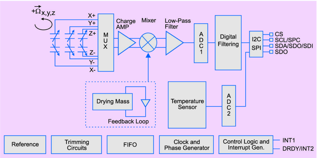
A representative MEMS device is A3G4250D IC from ST Microelectronics, a low-power three-axis angular rate sensor that provides a high degree of stability at zero rate level and with high sensitivity over temperature and time, shown in Fig. 5. It provides 16-bit digitised sensor information to the user’s microprocessor via a standard SPI or I2C digital interface, depending on the chosen version. With its tiny size of just 4mm×4mm, operation from a 1.8V supply, and stability and accuracy specifications, it is well-suited for inertial automotive navigation when combined with a three-axis accelerometer, for a complete six-axis IMU.
The autonomous car must be able to see and interpret what is in front when going forwards (and behind when in reverse, of course). It is also necessary to see what is on either side. In other words, it needs a 360-degree view. An array of video cameras is the obvious choice, plus a camera to determine where the lane is and sense objects or markers on the road.But using cameras alone presents problems. First, there are mechanical issues of setting up multiple cameras correctly and keeping these clean. Second, heavy graphic processing is needed to make sense of images. Third, there is a need for depth perception as well as basic imaging. And finally, conditions of lighting, shadows and other factors make it very challenging to accurately decide what the camera is seeing.
Instead, the primary vision unit on the autonomous vehicle is a lidar system. To enable the split-second decision-making needed for self-driving cars, a lidar system provides accurate 3D information on the surrounding environment. Using this data, the processor implements object identification, motion vector determination, collision prediction and avoidance strategies. Lidar unit is well-suited to big-picture imaging, and provides the needed 360-degree view by using a rotating, scanning mirror assembly on the top of the car.
Lidar provides raw information using high-speed, high-power pulses of laser light that are timed with the response of a detector to calculate the distance to an object from the reflected light. An array of detectors, or a timed camera, can be used to increase the resolution of the 3D information. The pulse is very short to enhance depth resolution, and the resulting light reflections are used to create a 3D point-like cloud that is analysed to transform the data into volume identification and vector information.
The transformed result is then used to calculate the vehicle’s position, speed and direction, relative to these external objects, to determine the probability of collision and instruct appropriate action, if needed.
For close-in control, such as when parking, lane-changing or in bumper-to-bumper traffic, lidar system is not as effective. Therefore it is supplemented by radars built into the front and rear bumpers, and sides of the vehicle. Operating frequency for this radar is usually 77GHz, which has been allocated for this use, has good RF propagation characteristics and provides sufficient resolution.
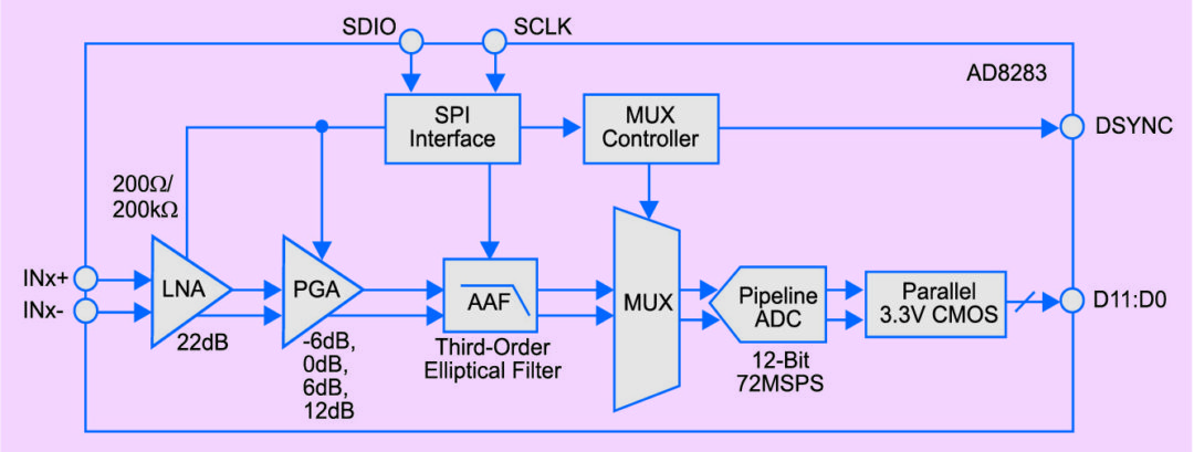
To fit the radar into the flat bumper assembly and its limited space, it is necessary to use a highly-integrated design, including using part of the radar sub-system PC board as its antenna. Also required are active components such as AD8283 from Analog Devices, which integrates six channels of LNA, a programmable gain amplifier (PGA) and an ant ialiasing filter (AAF) plus one direct-to-ADC channel, with a single 12-bit analogue-to-digital converter [(Figs 6 (a) and 6(b)].
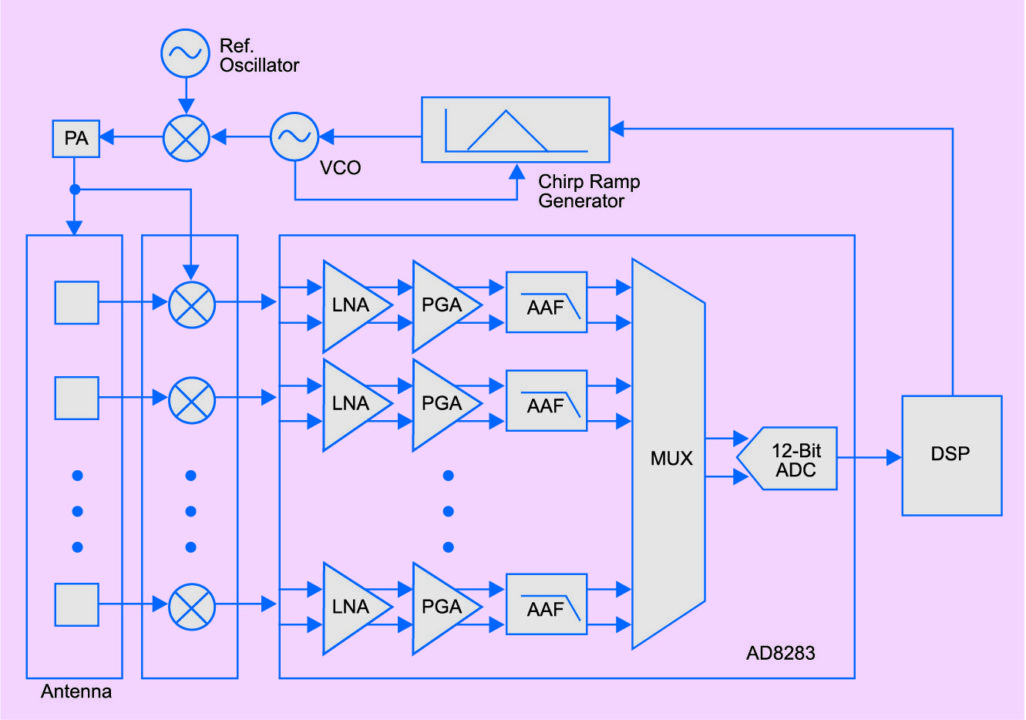
Automotive radar systems require sophisticated, controllable analogue front-end circuitry to handle reflected pulse signals across multiple receiver channels, and AD8283 from Analog Devices, which is designed specifically for this situation.
Primary application for AD8283 is in high-speed ramp, frequency-modulated, continuous-wave radar (HSR-FMCW radar). Performance of each functional block is optimised to meet the demands of this radar system with a careful balance among parameters such as LNA noise, PGA gain range, AAF cutoff characteristics, and ADC sample rate and resolution.
The AD8283 includes a multiplexer in front of the ADC, which automatically switches between each active channel after each ADC sample has been taken. Each channel features a gain range of 16 to 34dB in 6dB increments and an ADC with a conversion rate of up to 72MSPS (mega samples per second). The combined input-referred noise voltage of the entire channel at maximum gain is 3.5nV/√Hz, which is a critical threshold parameter for effective performance.
While components and sub-systems used for navigation and guidance, or for image-capture and sensing, get the most attention due to their glamour aspects, a large portion of the design of an autonomous vehicle involves mundane issues such as power management. Several application-specific, unique circuit boards and sub-systems are added to a conventional vehicle to provide the functions needed for autonomous operation. Much of the system-level operation involves measuring and managing the power requirements to control power, overall consumption and thermal dissipation.
Monitoring the current and voltage at the batteries often requires isolated sensing, for safety and functionally, but isolation is not needed on low-voltage circuit boards. Instead, the most common technique used to determine current at a source or load is with a high-side, current-sense, milli-ohm resistor (called a shunt) in conjunction with a differential amplifier that measures the voltage drop across it.
Although the amplifier is used with a discrete sense resistor, there is now an alternative that saves space, minimises errors in readings that are primarily due to the thermal drift of the sense resistor as it self-heats and simplifies the bill of materials by reducing the number of parts. INA250 from Texas Instruments puts a sense resistor and differential amplifier in a single package, resulting in a far-smaller board-layout footprint, fewer circuit-layout problems and lower system cost due to simplified schematic (Fig. 7).
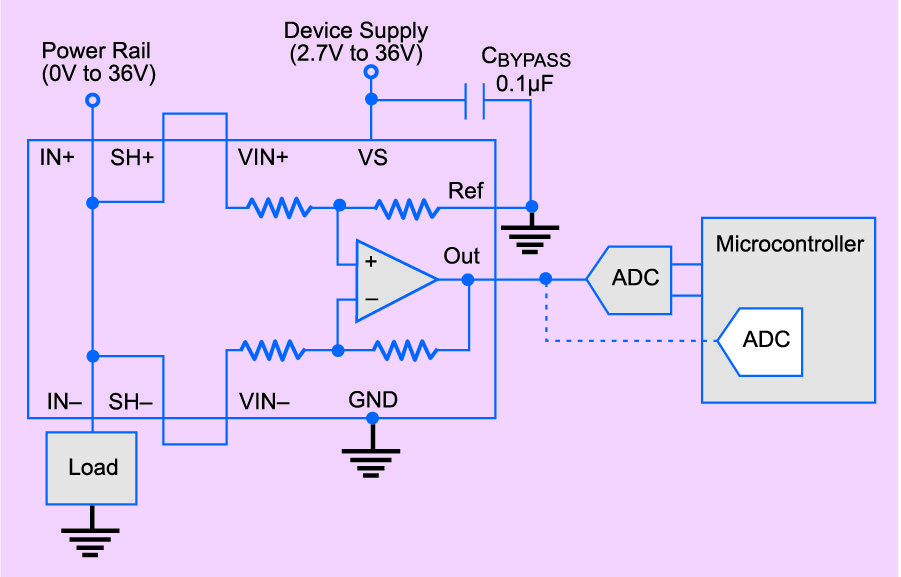
The INA250 current-sense resistor plus differential amplifier components ease the design and PC-board layout tradeoffs while guaranteeing high precision and accuracy along with lower cost.
A distributed solution
The complex distributed solution included the architecture of a Web based tool for manual and semi-automated ground-truth data validation. This Web based tool included a server application, a pre-processing unit and a graphical user interface that would provide the main interface for human testers. In addition, Saguaro provided data inspection for, and delivery of, validated ground-truth data.
To achieve the results, recordings were broken into individual images and then software tools were applied to present and edit the images very rapidly and accurately. Some technologies and techniques used for this solution were:
1. Distributed software applications
2. Distributed databases
3. HADOOP clusters
4. State-of-the-art JavaScript frameworks for the user interface, using three different backend approaches: based on Windows and using C#, based on Linux and Java, and based on Linux and Python
The complex distributed solution comprised three main components: a server backend, database and Web client application, all designed to allow for interaction with human testers.
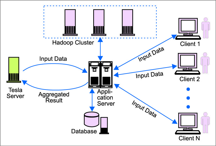
The server backend is responsible for connecting and getting input data from company servers. The server application streams data from a company server, separates streamed data into smaller pieces using the company’s API, assigns frames to individual clients, serves more than 100 client applications with requested data, aggregates output results from Web clients and sends the results to company servers. Client applications can be configured to send data in pre-defined sequences such as time-continuous or random.
The database is used by the server backend to store multiple types of data, including Big Data from numerous environmental sensors.
The Web client application enables the human tester to validate the target features identified in the current frame.
Putting together this solution requires engineers to use and coordinate multiple technologies including:
1. C#/.Net 4.5
2. Entity Framework
3. Log4Net
4. XML
5. MD5 encryption for DB credential
6. Windows Server 2012 R2
7. HTML5
8. CSS
9. JavaScript
10. Model/View/View ModelJSON/ React (Bootstrap)/Backbone
11. NodeJS
Although this particular solution is designed to meet the specific needs of advanced driver assistance systems and ground-truth validation, similar technologies, methodologies and technical capabilities can be used to develop other complex sensor based and machine learning applications. The most common applications could include solutions for the IoT.
Car manufacturers have made significant advances in the past decade towards making self-driving cars a reality. However, there still remain a number of technological barriers that manufacturers must overcome before self-driving vehicles are safe enough for road use.
GPS can be unreliable, computer vision systems have limitations to understanding road scenes and variable weather conditions can adversely affect the ability of onboard processors to adequately identify or track moving objects. Self-driving vehicles are also yet to demonstrate the same capabilities as human drivers in understanding and navigating unstructured environments such as construction zones and accident areas.
These barriers, though, are not insurmountable. The amount of road and traffic data available to these vehicles is increasing, newer range sensors are capturing more data and algorithms for interpreting road scenes are evolving. Transition from human-operated vehicles to fully self-driving cars will be gradual, with vehicles at first performing only a sub-set of driving tasks such as parking and driving in stop-and-go traffic autonomously. As the technology improves, more driving tasks can be reliably outsourced to the vehicle.
