Electronic filters are circuits that are designed to pass certain frequencies or frequency ranges while rejecting others. They are used in a wide range of applications, including audio processing, image processing, and telecommunications.
Different types of Electronic Filter
- Low-pass Filters
- High-pass Filters
- Band-pass Filters
- Band-stop Filters
Low Pass Filter:
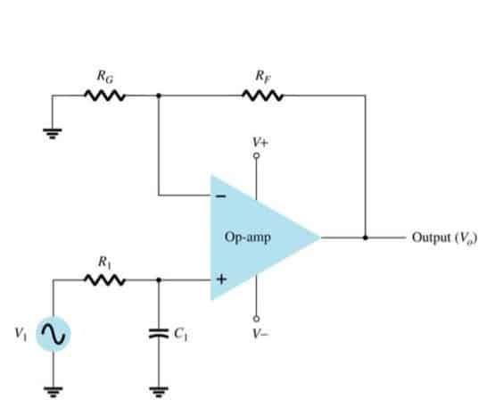
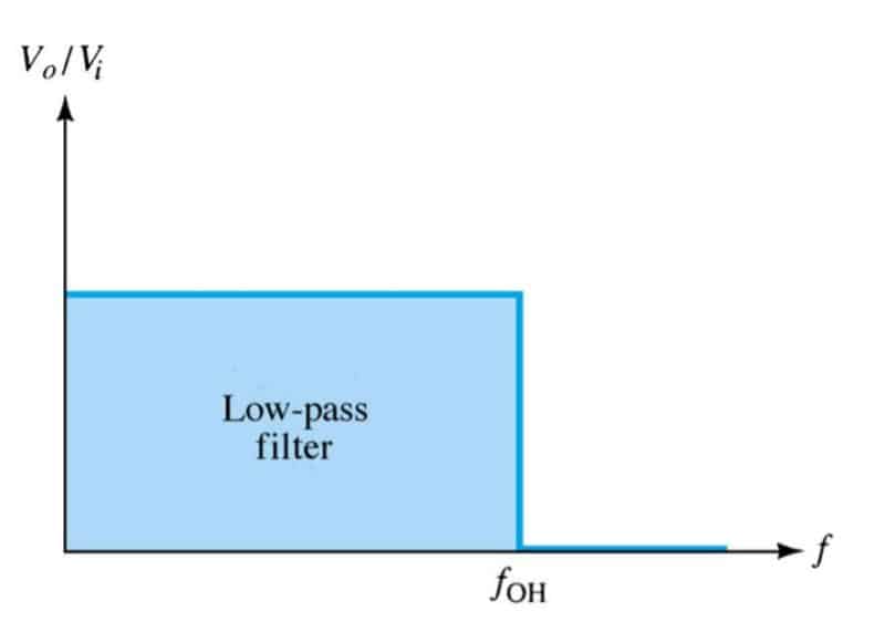
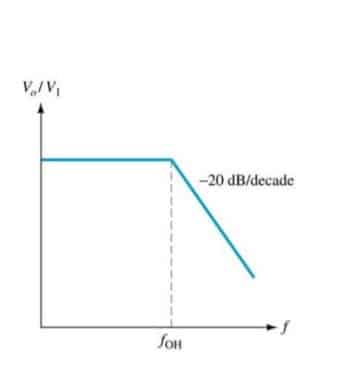
A Low pass filter (LPF) is used in circuits that only allow low frequencies to pass through. It is often used to block high frequencies and AC currents in a circuit. Given below is a sample LPF circuit using op-amp. Ideally, the frequency output of an LPF is like this, but this is not the case with real circuits. As there is a slight attenuation. This attenuation can be further minimized by adding multiple stages as below.
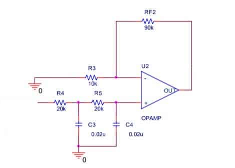
LPF is popular with speakers to block high pitches, some electric guitars, and radio transmitters.
High Pass Filter
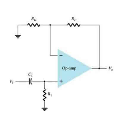
A high pass filter is used in circuits that only require high frequencies to operate. It blocks most low frequencies & DC components. Given below is a sample high-pass filter circuit using op-amp.
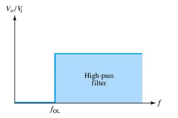
Ideally, the frequency output of a high-pass filter is like this,
But this is not the case with practical circuits. As there is a slight attenuation.
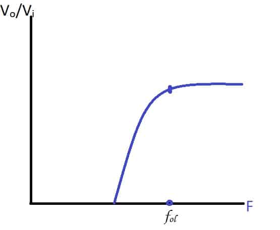
This attenuation can be further minimized by adding multiple stages as with LPF.
Band Pass Filter
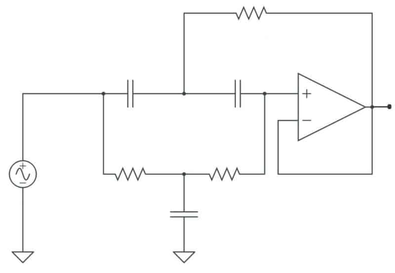
A band pass filter is a combination of a high pass and an LPF. It allows only a selected range of frequencies to pass through. It is designed in such a way that the cut-off frequency of the LPF is higher than the cut-off frequency of the high-pass filter, hence allowing only a selected range of frequencies to pass through. Presented here is a sample band pass filter circuit using op-amp.
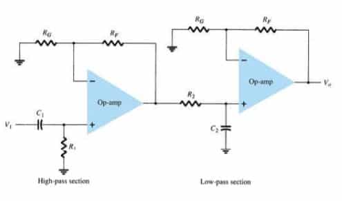
Ideally, the frequency output of a bandpass filter is like this,
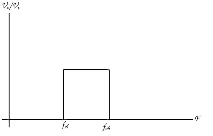
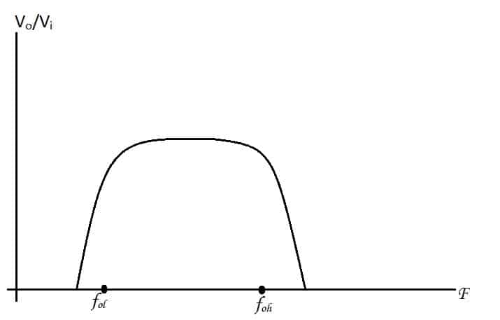
But this is not the case with practical circuits. As there is a slight attenuation.
The band-pass filter is popular with speakers to block high pitches, some electric guitars, and radio transmitters.
Band Stop Filter
A band stop filter also known as a notch filter is used in circuits that block only a selected range of frequencies and allows others to pass through. It would be an inverse of the band pass filter and can be created by using the same input at a high pass and an LPF.
Note: All graphs are plotted in the frequency domain
Electronic Filters – FAQs
Here are some common questions about electronic filters:
Q1. What is an electronic filter and how does it work?
An electronic filter is a device that removes or attenuates unwanted frequencies from an electrical signal. It does this by allowing a certain range of frequencies to pass through while blocking or attenuating others. Electronic filters can be either passive or active. Passive filters use passive components such as resistors, capacitors, and inductors to filter the signal, while active filters use active components such as transistors to amplify the signal as well as filter it.
Q2. What are the different types of electronic filters?
There are several types of electronic filters, including low-pass filters, high-pass filters, band-pass filters, band-stop filters, and all-pass filters. Each type of filter allows a different range of frequencies to pass through and blocks or attenuates others.
Q3. What are the applications of electronic filters?
Electronic filters are used in a wide range of applications, including audio and video processing, telecommunications, and instrumentation. They are also used in power supply circuits to remove unwanted noise and in radio frequency (RF) circuits to select a particular frequency band.
Q4. How do I choose the right electronic filter for my application?
There are several factors to consider when selecting an electronic filter for a specific application. These include the frequency range of the signal to be filtered, the amount of attenuation required, the type of filter response needed (e.g. low-pass, high-pass, etc.), the size and weight constraints of the system, and the power requirements of the filter.
Q5. What are the advantages and disadvantages of electronic filters?
The main advantage of electronic filters is their ability to remove or attenuate unwanted frequencies from a signal, which can improve the quality and clarity of the signal. However, electronic filters can also introduce phase shifts and distortion to the signal, and they may not be effective at blocking very high or very low frequencies.
This article was first published on 17 November 2017 and was recently updated on November 2023


I think that where you say: “This attenuation can be further minimised by adding multiple stages as with LPF.” that you mean “maximized” as in more attenuation. The signal would be minimized at a higher attenuation.